| date | desc |
|---|---|
| 3 Sep 2024 | initial |
This document describes a prototype Signals installation for a project involving WebRelay X-401 devices and an Alcatel VNA Server for panic buttons to be installed at Morgan State University.
The installation was performed using Signals and VNA Server instances associated with the internal ICON Cloud OTEC-1001 OXE server.
The existing Signals engineering document covering the X-401 was updated as part of this effort. A link to that document is found here.
This is not a complete project description. The purpose is to capture technical details specific to the handling of ControlByWeb X-401 devices, associated hardware (i.e. buttons) and external system communication within ICON Signals.
The project fundamentally involves handling alert events as follows:
ICON Signals can support additional functionality such as reporting missing devices. That topic will be covered later.
Most ICON Signals installations to date involving buttons have dealt with latched buttons as opposed to momentary contact buttons.
(3.1) A latched button is "pushed in" by the user, completing an electrical circuit, and stays pushed-in until the user releases it - either by a pulling-and-twisting mechanical action or by a second push which releases the latched button from its "pushed-in" state.
(3.2) With a momentary contact button, the electrical circuit is closed when the user presses the button and opened as soon as the user releases the button.
(3.3) For both types of buttons, a properly wired and configured X-401 can be triggered when the circuit is closed. The difference is that a latched button provides mechanical feedback, while a momentary button does not.
(3.4) An issue with momentary buttons is that users will often press them repeatedly. ICON Signals addresses this by using register values as described in the X-401 engineering note.
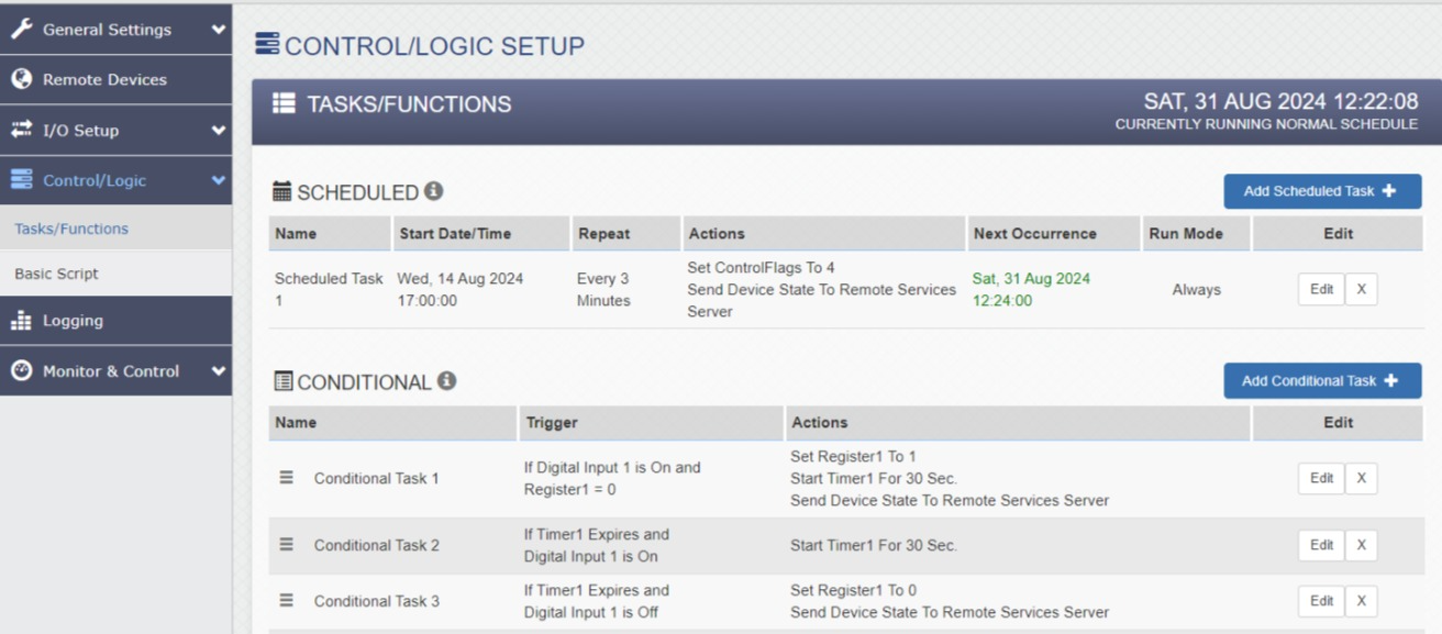
(3.5) The basic configured actions are outlined in the screenshots below. Further details are in the aforementioned engineering note.
Figure 3.5-1: Control/Logic
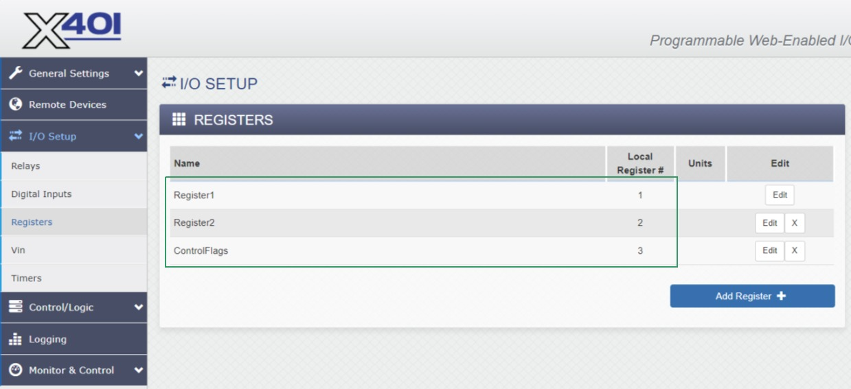
Figure 3.5-2: Registers
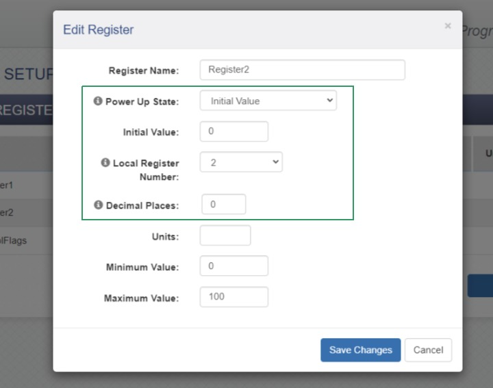
Figure 3.5-3: Register Config
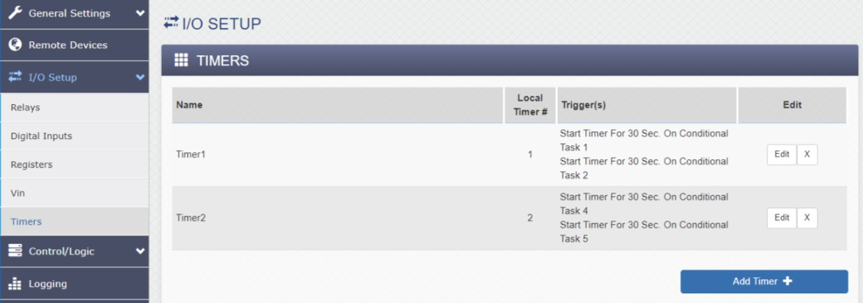
Figure 3.5-4: Timers
This section will briefly cover three items:
ICON Signals creates database entries for devices when it first receives data for them.
Note: the screen captures below were made several days after the X-401 devices were configured, disconnected and shipped to the customer.
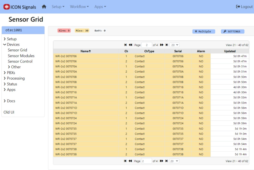
Figure 4.1-1: Sensor Grid
New devices within Signals must be configured and rules written to perform actions based on data received from the devices.
When a project involves a large number of similar devices, we can define one of them as a "template" and set other devices to be configured the same as the template device.
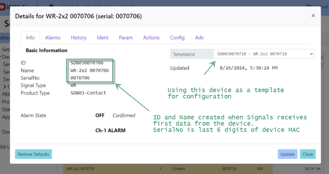
Figure 4.1-2: Device Info
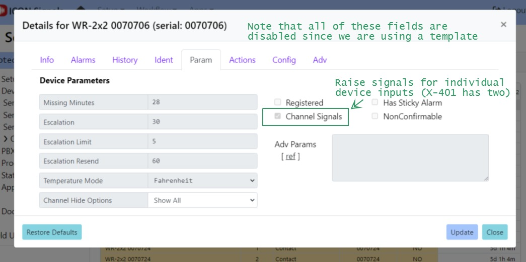
Figure 4.1-3: Device Params
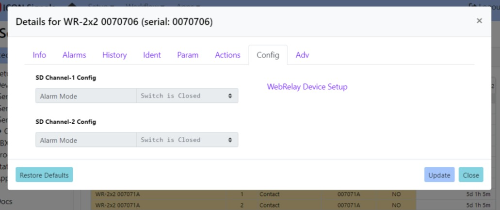
Figure 4.1-4: Device Config
When a device or device IO channel enters or leaves alarm state, ICON Signals raises a named "signal" and searches its rules list for a matching entry.
For example, when a button connected to input 1 on the X-401 device named WR-2x2 0070706 is pressed a signal is raised with the name:
WR-ON-CH1-%WR-2x2 0070706%This matches the regular expression for Rule 2 in the Rule List screenshot.
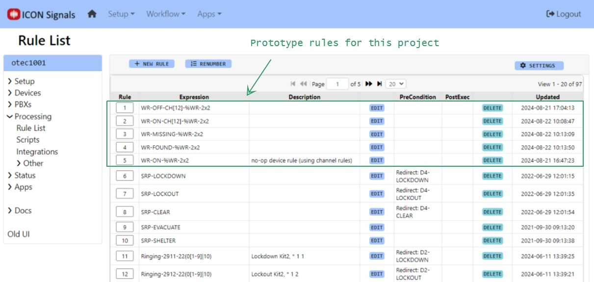
Figure 4.2-1: Rule List
When the rule is executed it sends a Rainbow message to a configured Rainbow bubble and executes a special action script. Often these scripts are used to do things like turn relays on or off, but in this case the script sends an HTTPS request to the VNA server.
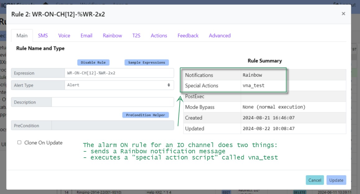
Figure 4.2-2: WR-ON Rule
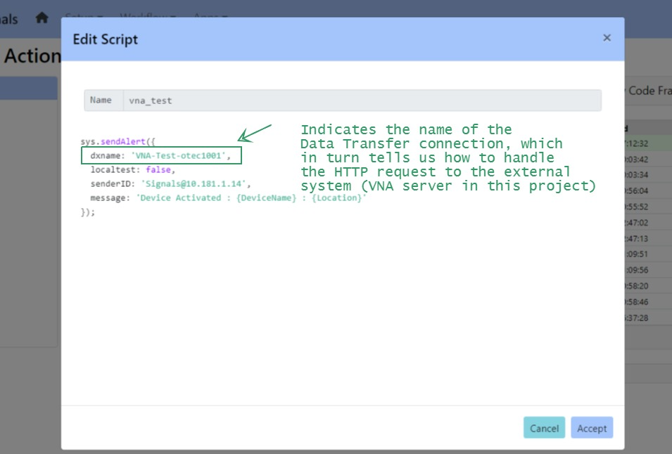
Figure 4.2-3: Action Script
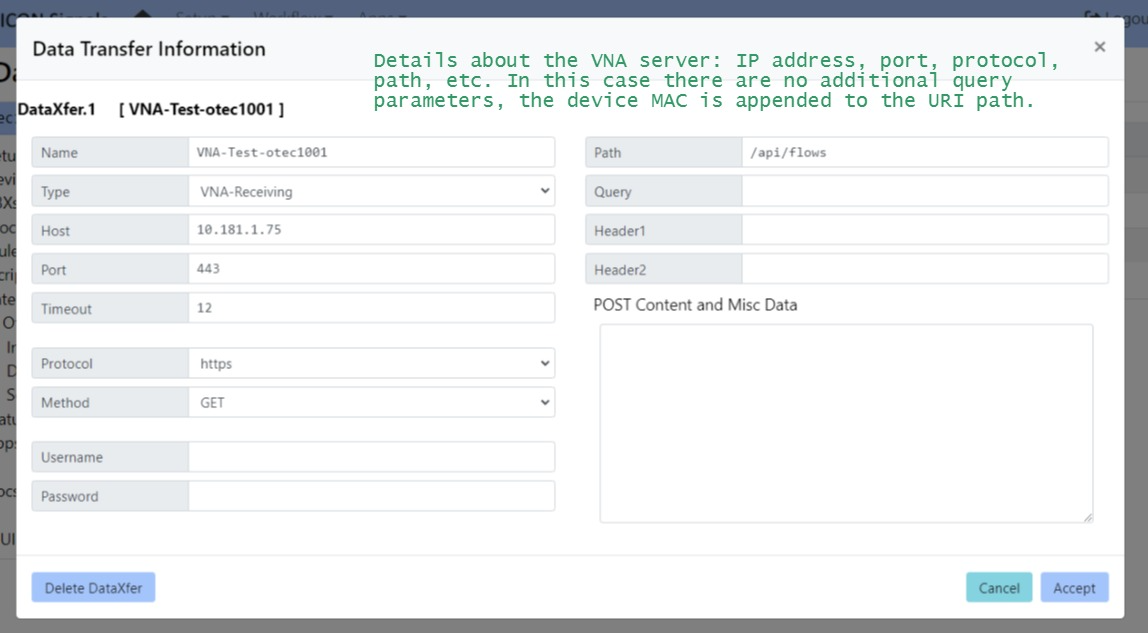
Figure 4.2-4: Data Transfer Connection
In our prototype setup, the VNA server sends an email notification and Signals sends a Rainbow message to a bubble. Screenshots below.
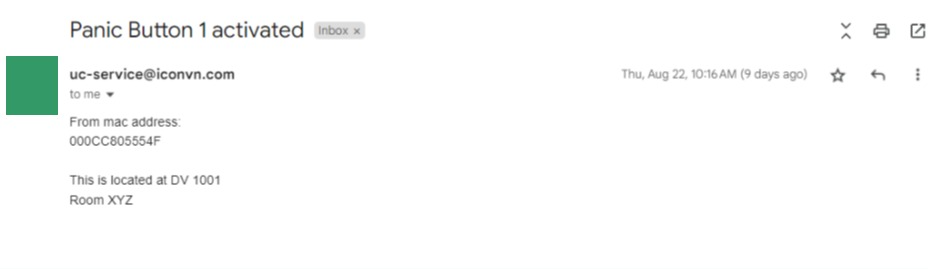
Figure 4.3-1: Email Notification from VNA Server
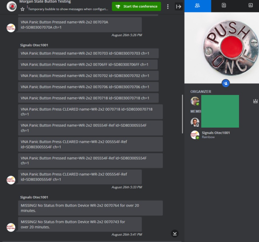
Figure 4.3-2: Rainbow Notification from ICON Signals
The main focus of this project involves sending button-press alerts to the VNA Server. ICON Signals can also provide other functions that may be useful.
We typically program X-401 devices to send a state data message to the ICON Signals server every 3 or 4 minutes as a heartbeat.
If no state data has been received from a device for a configured amount of time, a "MISSING" signal can be raised. If a matching rule is found in the rule list (see Figure 4.2-1), Signals will execute that rule - which will likely notify IT staff about the missing device.
Conversely, a "FOUND" signal will be raised, when data is received from a previously missing device.
Figure 4.3-2 contains an example "Missing" message to a Rainbow bubble. Email and SMS notifications can also be sent to IT staff members.
Placing ICON Signals into "Test Mode" which can potentially have two effects:
The following screenshots illustrate this functionality. More detailed documentation is available.
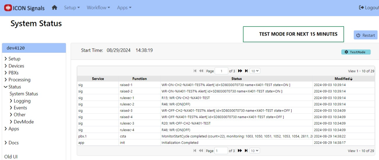
Figure 5.2-1: Setting Test Mode
TEST MODE is a temporary setting subject to expiration. A technician can set the test mode time span to various values between 5 minutes and one hour.
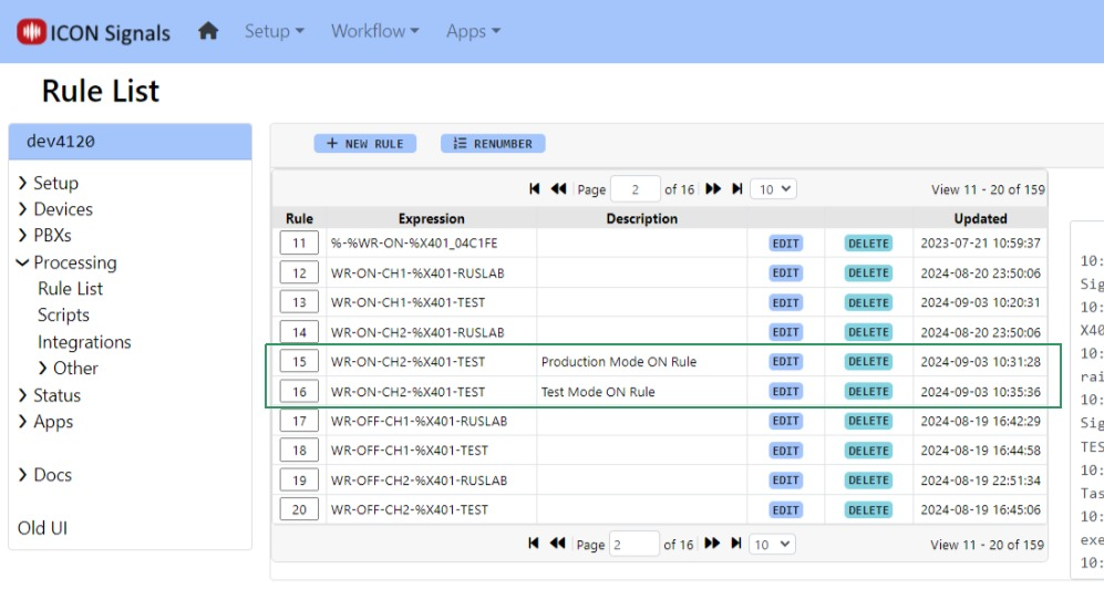
Figure 5.2-2: Production and Test Mode Rules
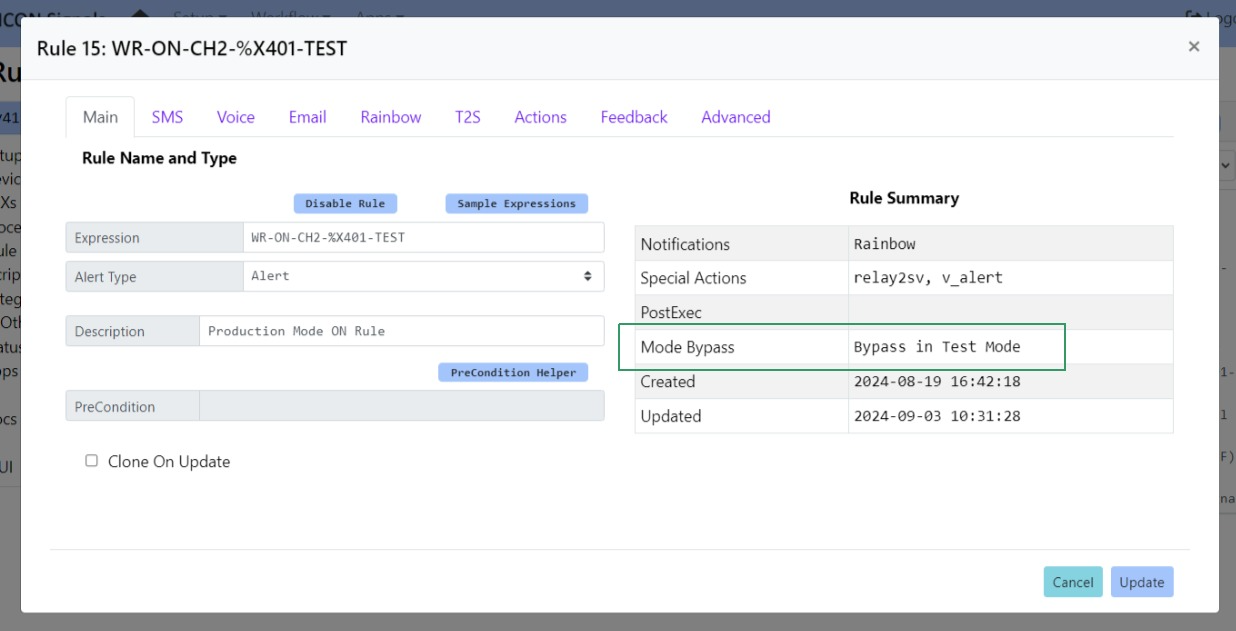
Figure 5.2-3: Production Mode Rule
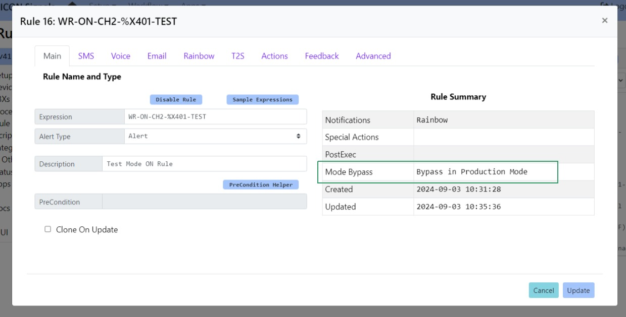
Figure 5.2-4: Test Mode Rule
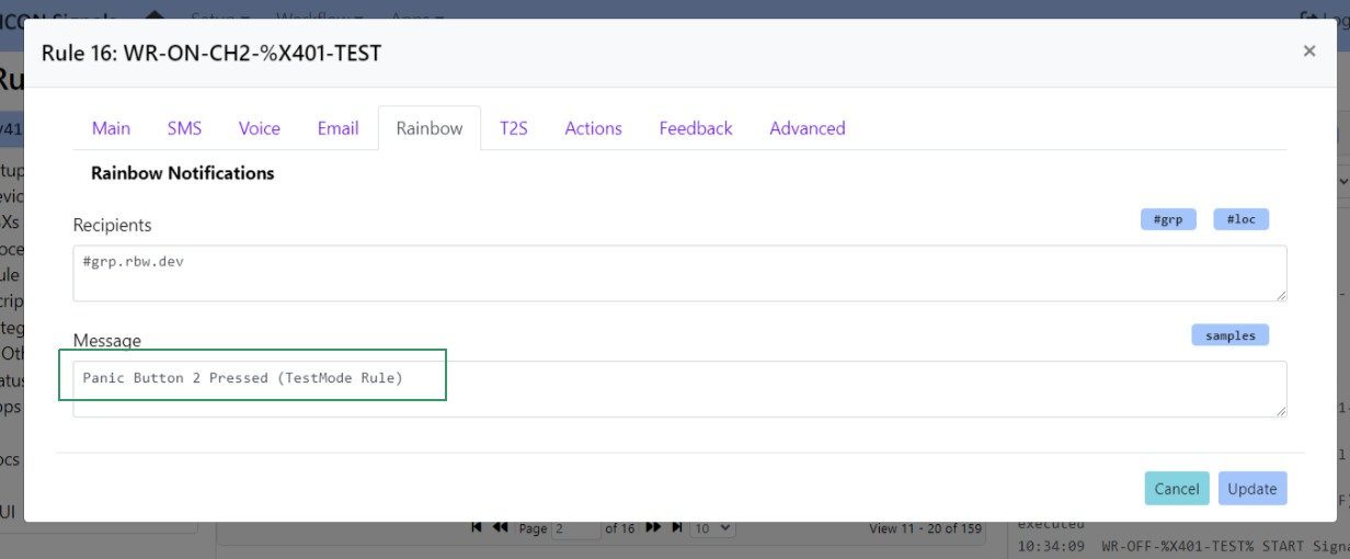
Figure 5.2-5: Test Mode Message
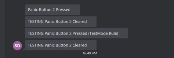
Figure 5.2-6: Mode-Specific Output
Note: For this example, we created a TestMode specific rule for the ON signal. The same OFF signal rule was executed for both test and production mode, but the "TESTING" prefix was still prepended in test mode.
(End of Document)
2024 ICON Voice Networks