| date | desc |
|---|---|
| 20 Aug 2024 | initial |
This document is specifically focused on the ControlByWeb X-401, which has two optically-isolated digital inputs and two relays.
The previous version of the document also dealt with older devices which are no longer sold. A link to the previous document is at the top of this page.
The main reason for an X-401-specific document is to discuss more details about the X-400 series firmware which is present in most, if not all, webrelay devices supporting dry contact functionality.
We almost always use the X-401-E, which is the PoE version of the device. There is no functional difference between PoE and non-PoE models, but there are differences based on firmware versions.
With the X-401 and all other 400-series ControlByWeb devices, we use Remote Services functionality to send data to the ICON Signals server.
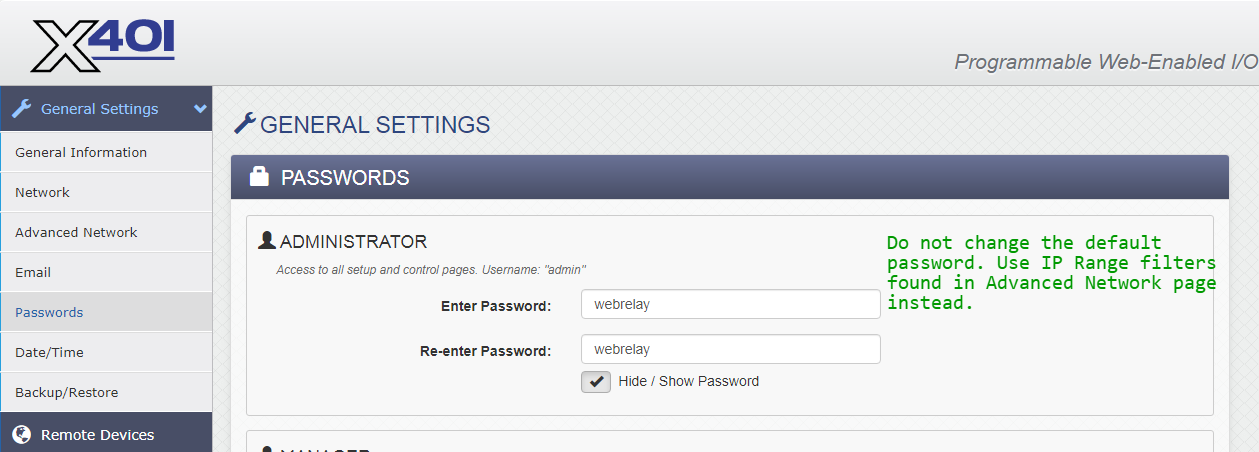
One useful feature of the X-401 is IP address filtering to control which hosts can send commands to the device.
ICON Signals has no visibility into WebRelay device settings and assumes they are configured as described in this document.
Other WebRelay products will not work with ICON Signals until we write software to support them.
This document will include screenshots of the WebRelay interfaces when discussing their use within ICON Signals, but will not describe all features of those products.
Product documentation is available at: https://www.controlbyweb.com
ICON Signals supports different families of sensor devices,
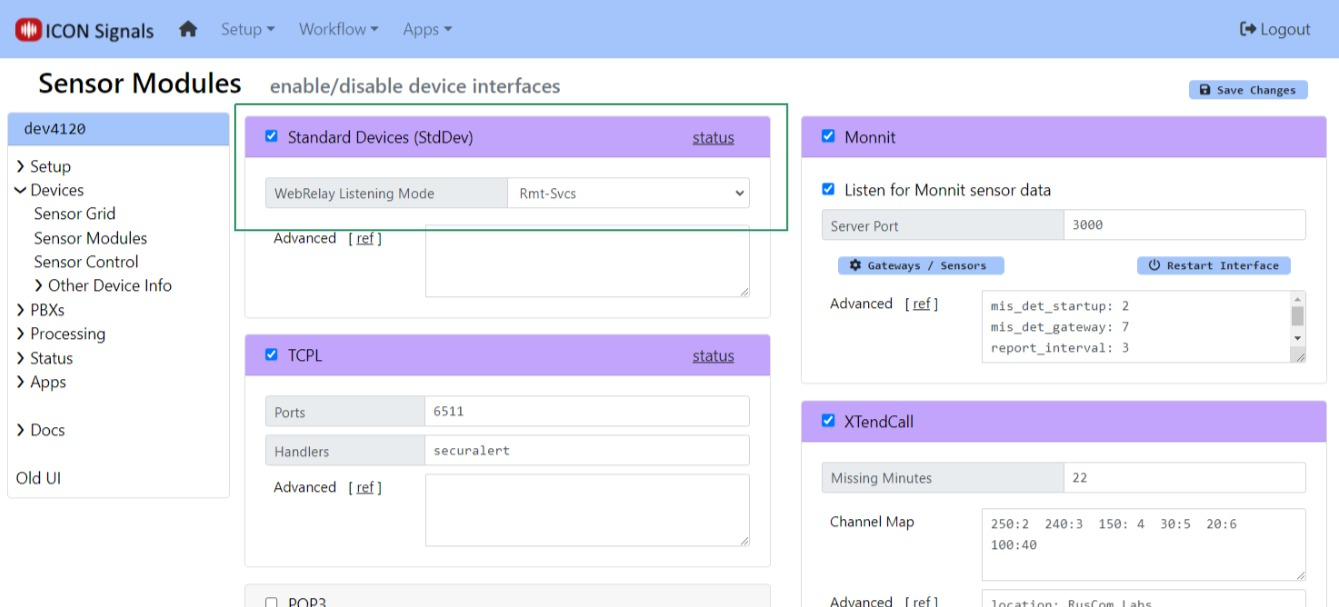
each of which can be enabled or disabled in the Workflow > Sensor Modules page. The Standard Device Interface is used for devices which are not directly configured by ICON Signals itself. Examples include passive environmental sensors, webcams, and other devices which are configured outside of ICON Signals and which simply send data to ICON Signals.
The WebRelay devices are handled within the Standard Devices Interface. When this interface is enabled, Signals does the following with respect to webrelay devices:
(Note: Changing the Remote Services port from 6506 to another value is not recommended and should only be done in consultation with ICON support.)
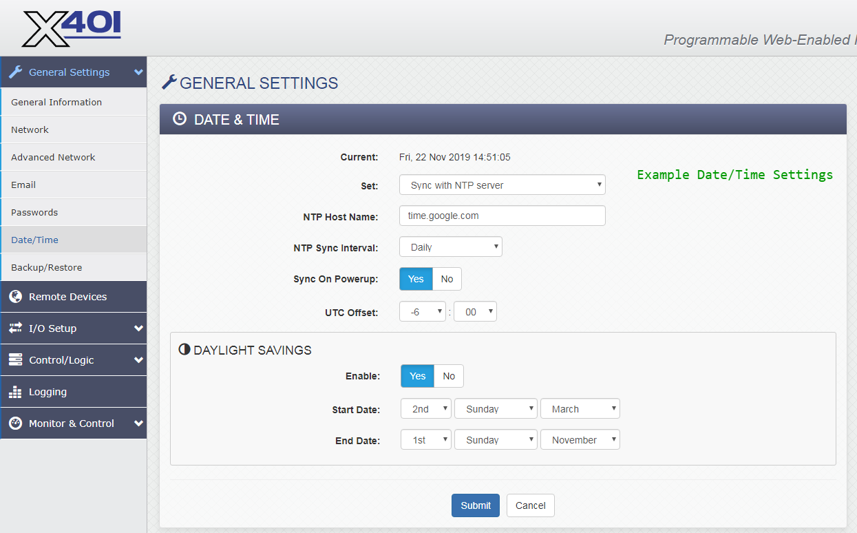
X-401 devices will be configured to enable Remote Services and send data to the Signals server on port 6506.
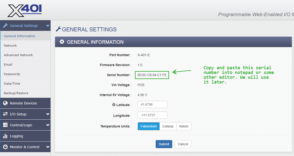
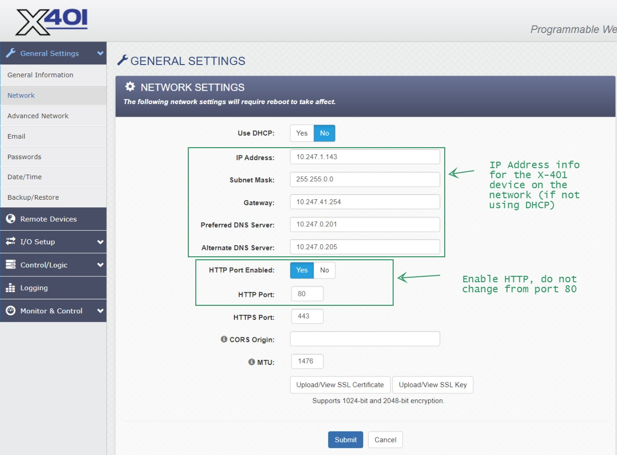
Configure the WebRelay device to be on the same network as the ICON Signals server. Refer to the manual for details.
For all devices, the setup page is {ip-address}/setup.html
Follow the "Quick-Start Guide" shipped with the device to get it on the same network as the ICON Signals server. Then continue reading this section.
The screenshots below show the changes needed to work with Signals.
When making any changes, you must click the Submit button at the bottom of the page.
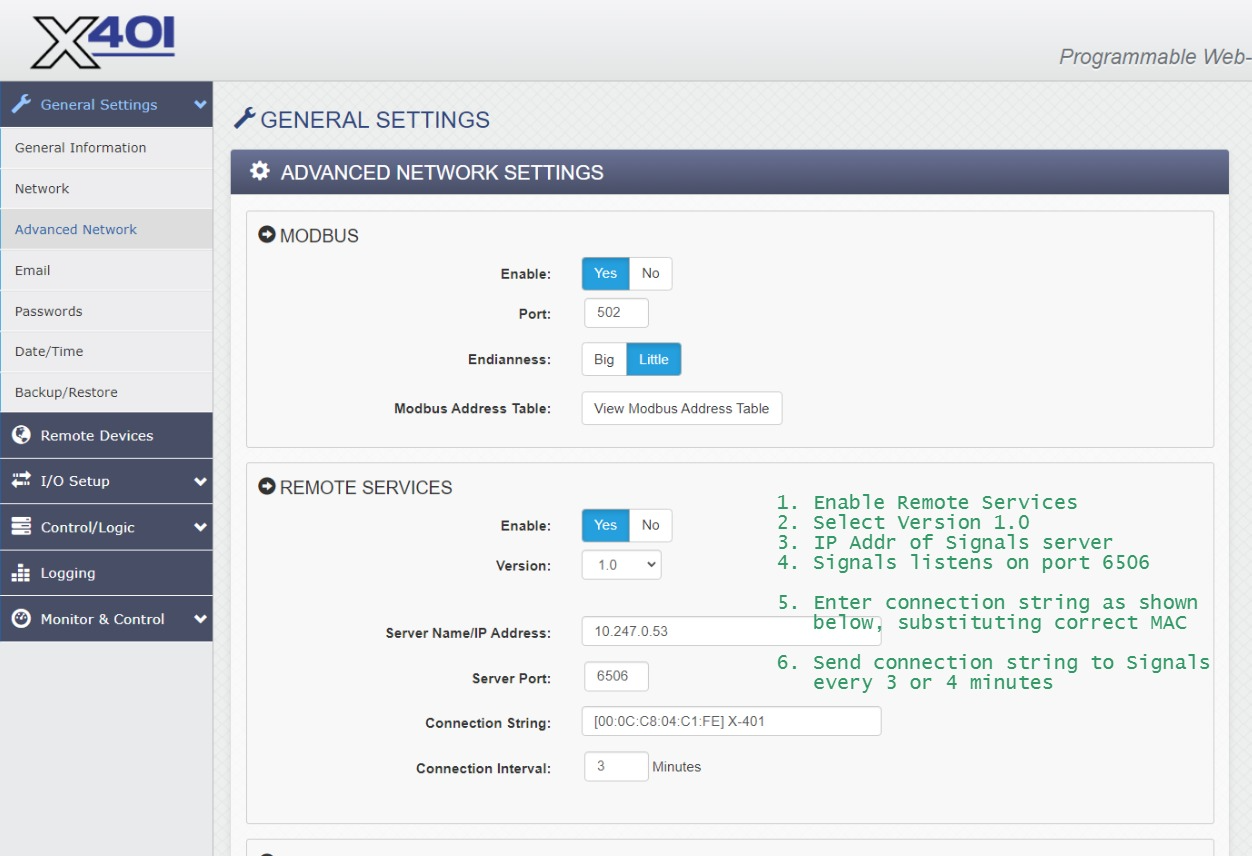
When Remote Services is enabled, the WebRelay makes a TCP connection to the given IP address and port and sends the connection string. After that it periodically sends the connection string to the destination server. ICON Signals expects to find the MAC address in the connection string, so please configure it as shown in the above screenshot.
No changes are needed in this section for interoperation with Signals.
Each section of IO Setup is briefly covered below.
Two different types of buttons may be connected to an X-401: latched and momentary contact.
For latched buttons, no changes are needed. However a control flags register may be useful depending on specific system details.
(3.4.1) Relays
No changes needed in this section.
(3.4.2) Digital Inputs
For momentary buttons, consider reducing the default Hold Time from 20ms to something shorter (e.g. 10ms or 5ms). This parameter is under Advanced Features.
(3.4.3) Registers
NOTE: Registers are used with momentary buttons. If your site is using latched buttons, you can ignore this section.
Register 1 is pre-defined on the X-401. Create Register 2 and Register 3 as well.
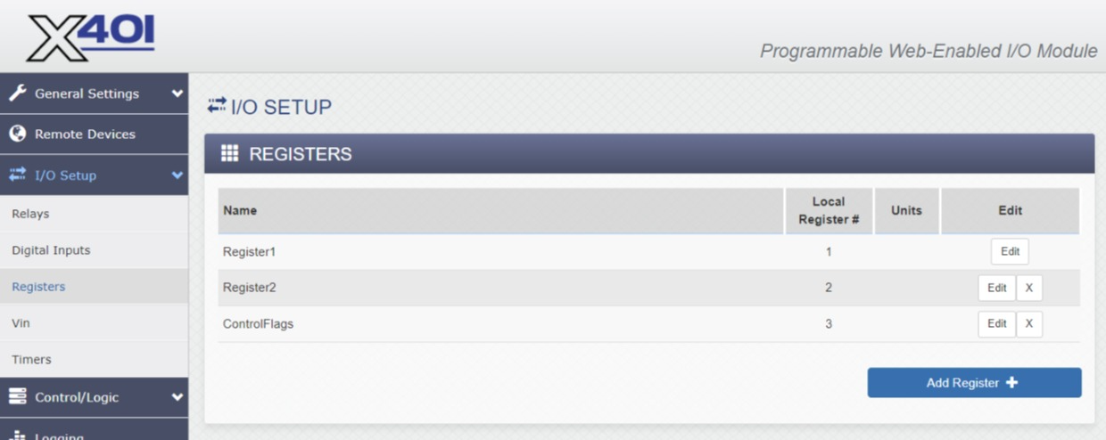
You can name the registers anything you want, but the local register numbers must be 1, 2 and 3.
Configure all three registers with:
Initial Value00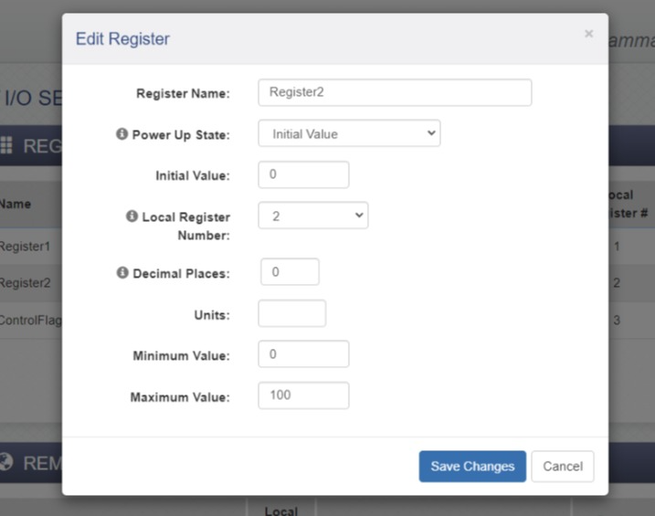
As shown in the register list, Register 3 is used to hold flag bits. It may have a non-zero Initial Value.
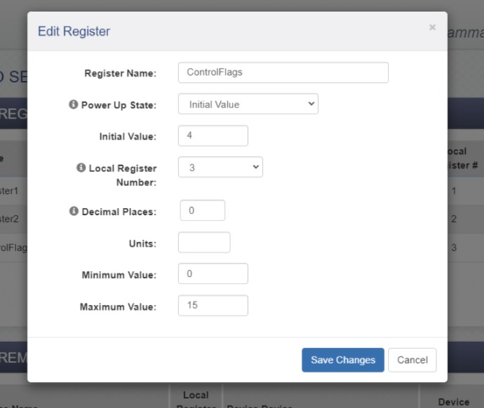
Control bits are shown in the table below.
| bit | name | desc |
|---|---|---|
| 0x8 | NADR | non-addressible device (cannot be polled by Signals) |
| 0x4 | UREG | use register1 and register2 values in place of digitalInput1 and digitalInput2 respectively |
| 0x2 | URS | use relay1 and relay2 values in place of digitalInput1 and digitalInput2 respectively |
| 0x1 | DBG | internal debugging flag |
For momentary buttons, Register3 should have an initial value of 4. Add 8 if the device is non-addressible.
(3.4.4) Vin
No changes needed in this section.
(3.4.5) Timers
Timers are used for momentary buttons. If your site has latched buttons you can ignore this section.
Otherwise, create two timers. They do not need to be configured.
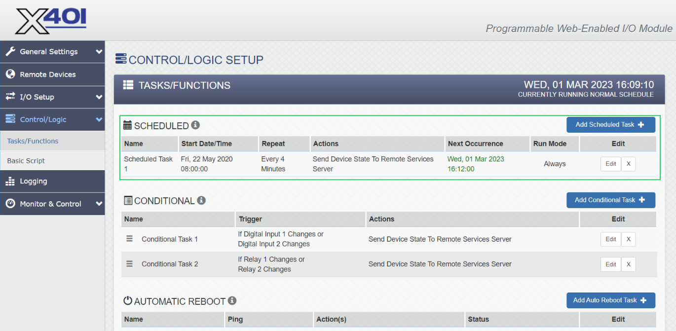
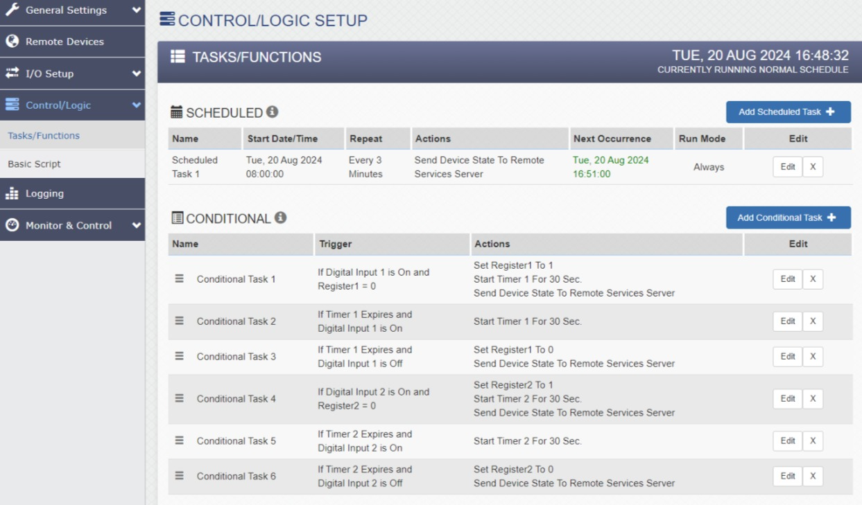
The Control/Logic Setup > Tasks/Functions page is critical to
the integration with Signals.
We configure the X-401 to send state information to the Signals server both periodically and whenever either digital input has a change of state (ON or OFF).
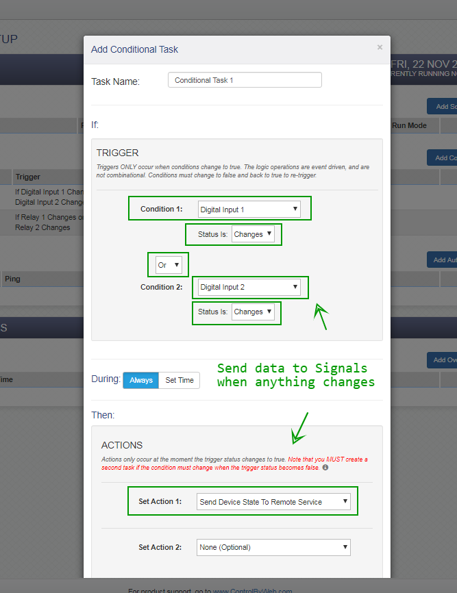
(3.5.1) Latched Buttons
The following screenshots show a configuration suitable for latched buttons.
Basically we want to send the state data to Signals via Remote Services whenever an input changes.
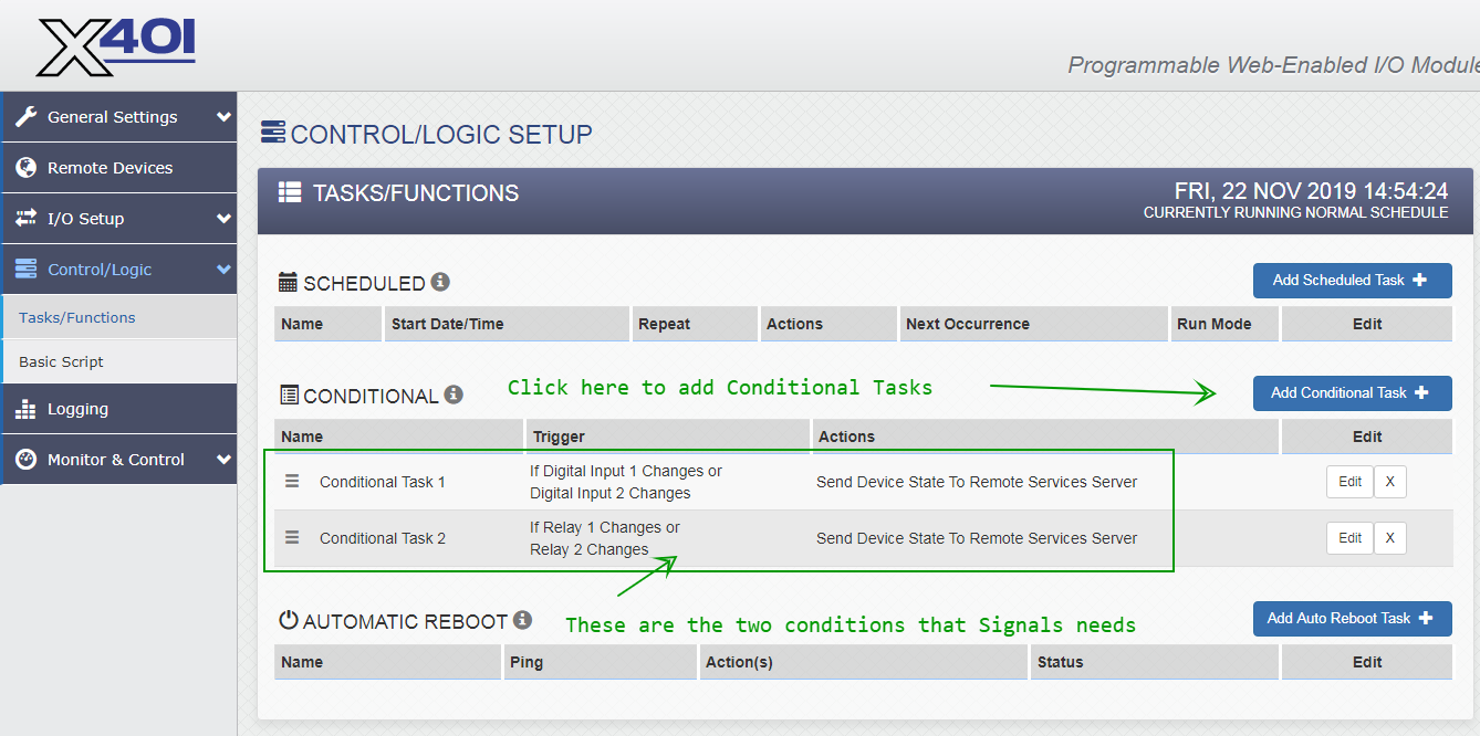
NOTE: The screenshots above include a conditional task to send data to Signals for relay state changes, but that is not strictly necessary.
(3.5.2) Momentary Contact Buttons
This is a more complicated configuration scenario. We want to guard against repeated button presses.
The basic idea is use register values in place of input values. For example, when a button is pressed and digitalInput1 changes from 0 to 1:
register1 value to 1timer1 to 30 (30-second countdown timer)The register1 value of 1 is sent in the state data push to ICON Signals - which uses it as the input 1 value.
When timer1 expires (reaches 0), register1 is set back to 0 and the state data which now indicates a clear condition is pushed to Signals again.
The following screenshot encapsulates this logic and also guards against the use case of a momentary button held down as well as a scheduled periodic state push occurring in the middle of an alarm condition.
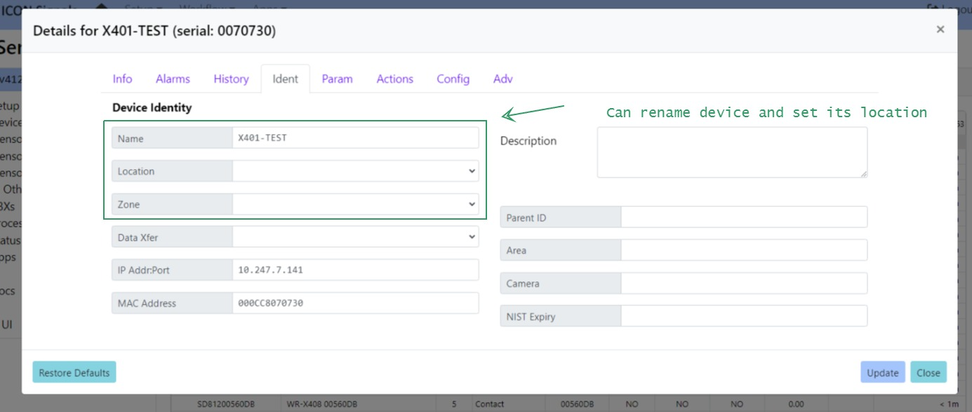
If the X-401 is sending data to ICON Signals, then a new device will appear in the Sensor Grid.
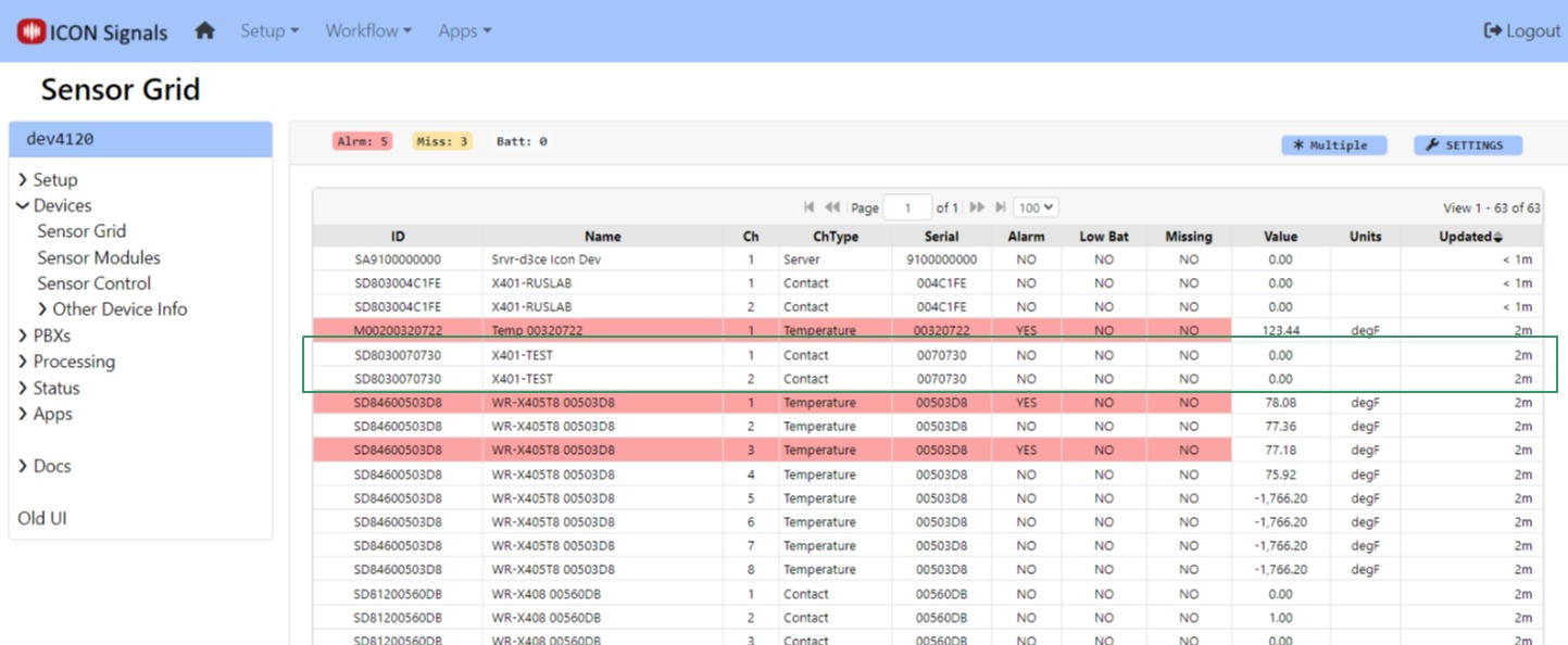
Click on the device to set name and location as well as to define which state(s) represent an alarm condition.
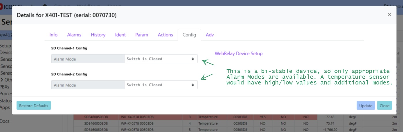
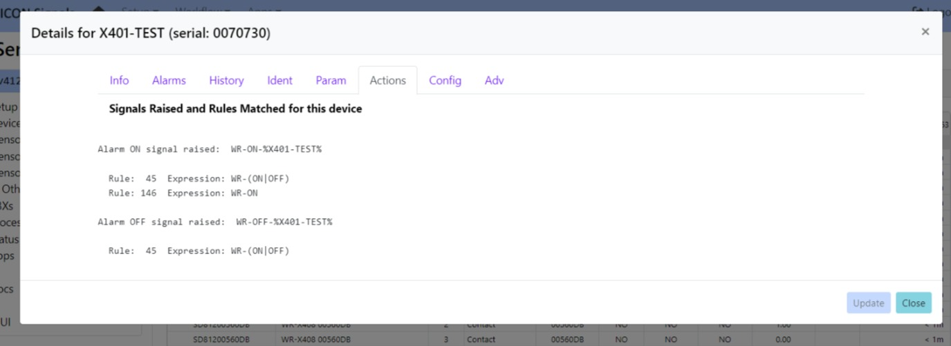
When the WebRelay device goes into an out of alarm state, ICON Signals raises the signals shown in the Actions tab. If we were using Web Relay devices to trigger a lockdown, we would likely create a rule with the expression WR-ON (which would match against all WebRelay devices) and redirect it to our LOCKDOWN rule.
The WebRelay device relays can be configured to mirror the associated input state. (e.g. Switch closes, relay turned on, stobe light is lit). But what if you need programmatic control of the relay? For example, the relay is not turned off until a lockdown command is received.
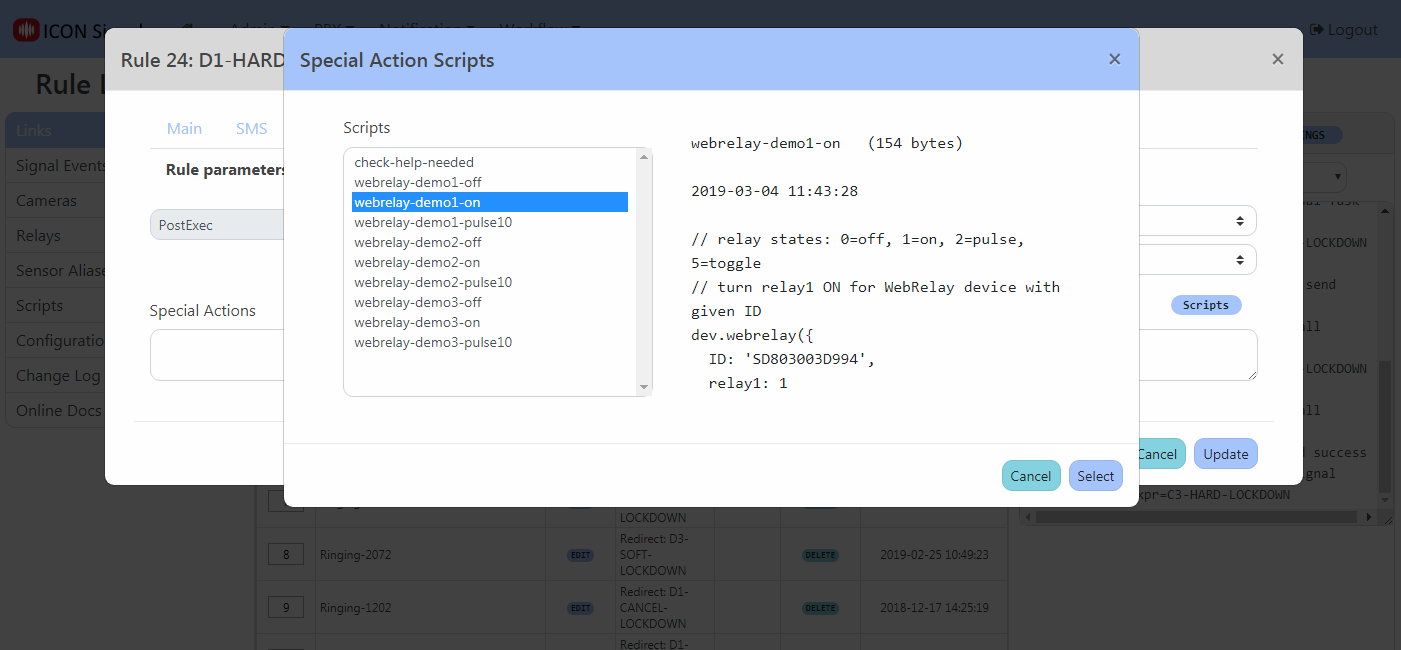
Special actions are very short scripts included in a rule to perform actions outside of what's available in the user interface.
In this case, a new signals script API function called stddev.webrelay() can be used to do anything allowed by the WebRelay device. The script can turn either relay on or off, toggle the value, or pulse a relay for a specified duration.
Example screenshots follow.
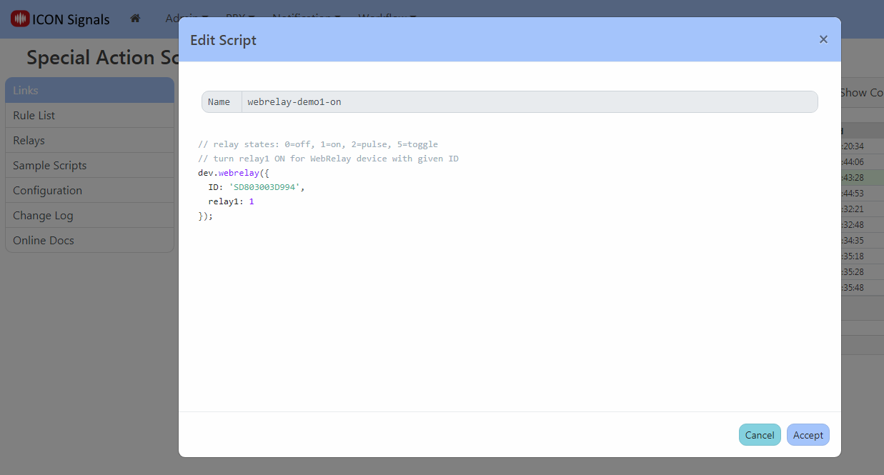
stddev.webrelay() parameters for WebRelay-Dual (X-301 and X-401)| ID | Device ID |
|---|---|
| relay1 | 0=off, 1=on, 2=pulse, 5=toggle |
| pulse1 | pulse time (secs) for relay 1 in pulse mode |
| relay2 | 0=off, 1=on, 2=pulse, 5=toggle |
| pulse2 | pulse time (secs) for relay 2 in pulse mode |
If a pulse duration is not provided as a parameter, the device uses its configured default value.
stddev.webrelay() parameters for WebRelay (X-WR-1R12)| ID | Device ID |
|---|---|
| relay | 0=off, 1=on, 2=pulse, 5=toggle |
Unlike the X-301, pulse duration can only be configured in the device itself.
                  +----------------+
                  |                |
                  +                |
         o+------+o Vout           |
Contact 1           Gnd  o+----+   |
         o+------+o In1+       |   |
                    In1- o+----+   |
                               |   |
         o+------+o In2+       |   |
Contact 2           In2- o+----+   |
         o+--+                     |
             +---------------------+
2024 ICON Voice Networks