| date | desc |
|---|---|
| 18 Oct 2017 | initial |
| 3 Feb 2018 | Special Actions API |
| 2 Jul 2018 | X-WR-1R12 |
| 27 Aug 2019 | Added dry contact wiring appendices |
| 22 Nov 2019 | X-401 added, Signals UI images updated |
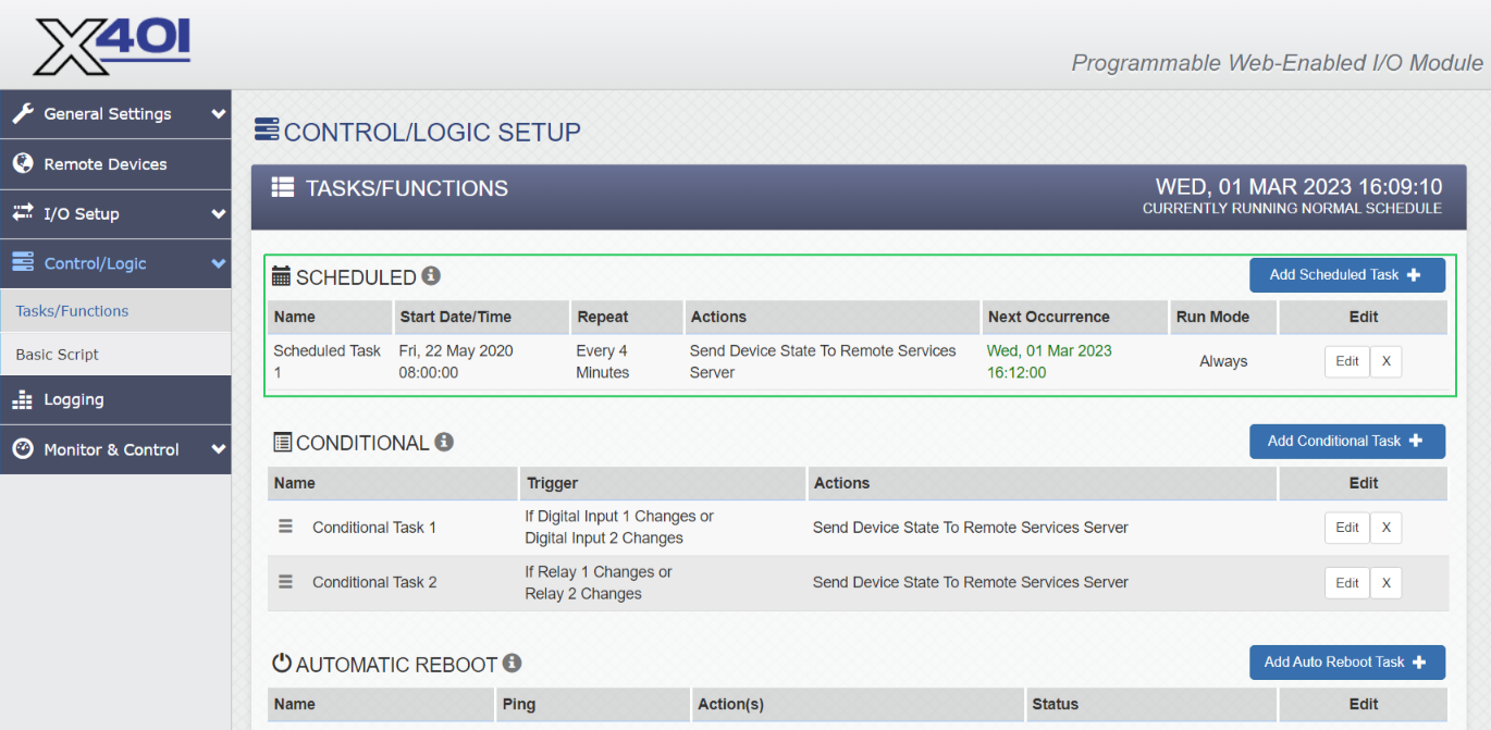
| 1 Mar 2023 | Added scheduled task verbiage and screenshot |
This document details configuration and operation of the ControlByWeb WebRelay products for dry contacting sensing and relay control by ICON Signals. The products currently supported for use with ICON Signals are:
X-301-E (two inputs & two relays w/ remote services)X-401-E (two inputs & two relays w/ remote services - replaces 301)X-WR-1R12-1I-E (one input & one relay, no remote services)These devices are PoE and have optically-isolated inputs.
The X-401 and X-301 (WebRelay-Dual) are more expensive, but have significantly better capabilities.
The X-WR-1R12-1I-E (WebRelay) has more limitations, but is less expensive.
A fundamental difference is that the X-401/X-301 appears designed to work with other systems via "Remote Services" while the WebRelay is really just intended to work with other WebRelay devices.
One useful feature of the X-401/X-301 is IP address filtering to control which hosts can send commands to the device. The WebRelay doesn't have this and shouldn't be used on a "shared" network where it could be subject to abuse.
ICON Signals has no visibility into how WebRelay devices are configured and assumes they are configured as described in this document.
The non-PoE versions of these devices should work with ICON Signals, although we have not tested them.
Other WebRelay products will not work with ICON Signals until we write software to support them.
This document will include screenshots of the WebRelay interfaces when discussing their use within ICON Signals, but will not describe all features of those products.
Product documentation is available at: https://www.controlbyweb.com
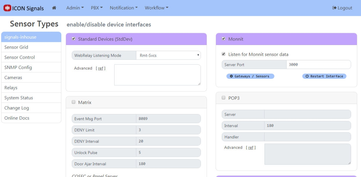
ICON Signals supports different families of sensor devices,
each of which can be enabled or disabled in the Workflow > Sensor Modules page. The Standard Device Interface is used for devices which are not directly configured by ICON Signals itself. Examples include passive environmental sensors, webcams, and other devices which are configured outside of ICON Signals and which simply send data to ICON Signals.
The WebRelay devices are handled within the Standard Device Interface. When this interface is enabled, Signals does the following with respect to webrelay devices:
(Note: Changing the Remote Services port from 6506 to another value is not recommended and should only be done in consultation with ICON support.)
WebRelay devices that do not have Remote Services (e.g. the 1-input, 1-relay WebRelay X-WR-1R12) do not use the WebRelay listener.
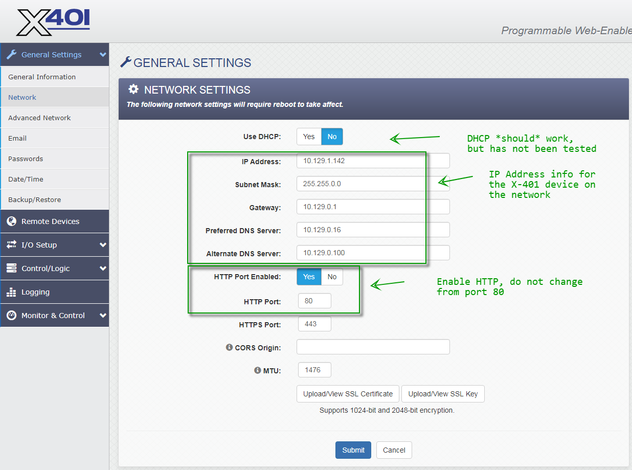
Configure the WebRelay device to be on the same network as the ICON Signals server. Refer to the manual for details.
For all devices, the setup page is {ip-address}/setup.html
Follow the "Quick-Start Guide" shipped with the device to get it on the same network as the ICON Signals server. Then continue reading this section.
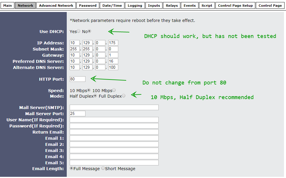
Screenshots from the WebRelay setup pages follow with relevant comments.
When making any changes, you must click the Submit button at the bottom of the page.
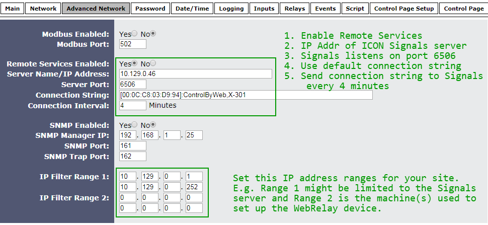
When Remote Services is enabled, the WebRelay makes a TCP connection to the given IP address and port and sends the connection string. After that it periodically sends the connection string to the destination server.
ICON Signals expects to find the MAC address in the connection string, so don't remove it. In fact, the only change that should be made to the connection string is to append the phrase "use-relay-state" if you want ICON Signals to use the relay state values in place of the input state values.
Set the IP Filters for your site. Refer to the WebRelay manual for details.
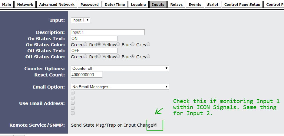
Most of the fields in the Inputs and Relays tabs are not used by ICON Signals.
The one thing that must be done is to check the "Send State Msg" checkbox at the bottom of the page.
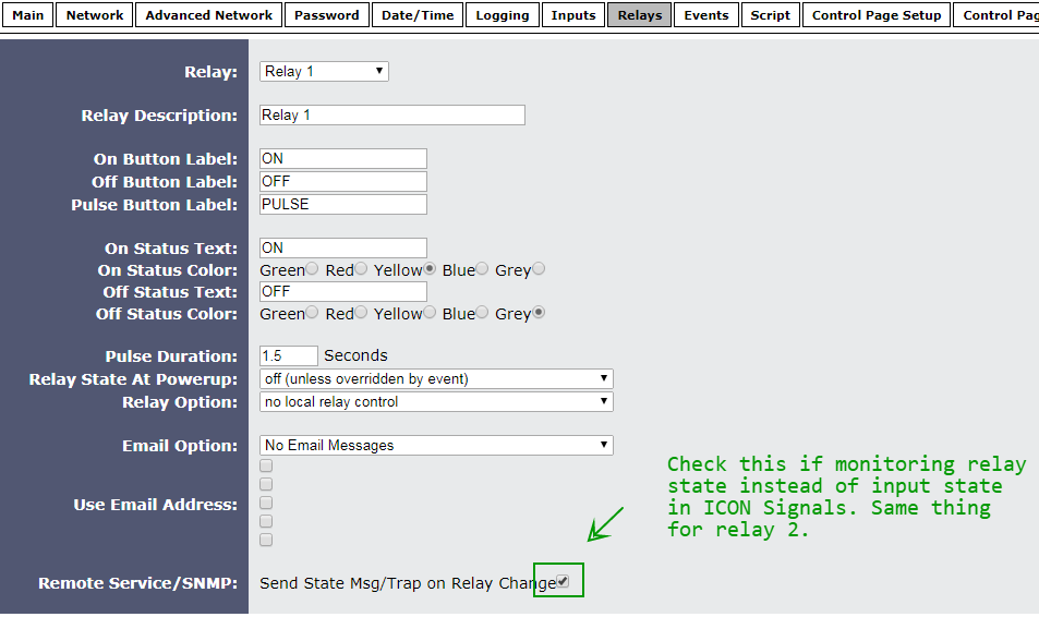
The WebRelay sends the states of both inputs and both relays to ICON Signals. If you want to monitor relay states instead of input states, two things must be changed:
Append use-relay-state to the connection string (see Advanced Network tab)
Check the "Send State Msg" checkbox at the bottom of the page. Repeat for Relay 2 if necessary.
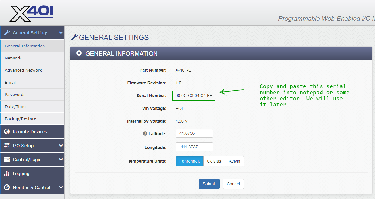
The X-401 is functionally similar to the X-301, but the configuration is completely different.
The screenshots below show the changes needed to work with Signals.
When making any changes, you must click the Submit button at the bottom of the page.
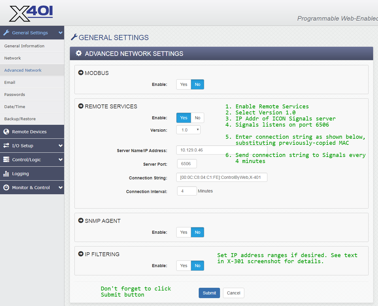
When Remote Services is enabled, the WebRelay makes a TCP connection to the given IP address and port and sends the connection string. After that it periodically sends the connection string to the destination server. ICON Signals expects to find the MAC address in the connection string, so please configure it as shown in the above screenshot.
The Control/Logic Setup > Tasks/Functions page is critical to
the integration with Signals.
We configure the X-401 to send state information to the Signals server both periodically and whenever either digital input has a change of state (ON or OFF).
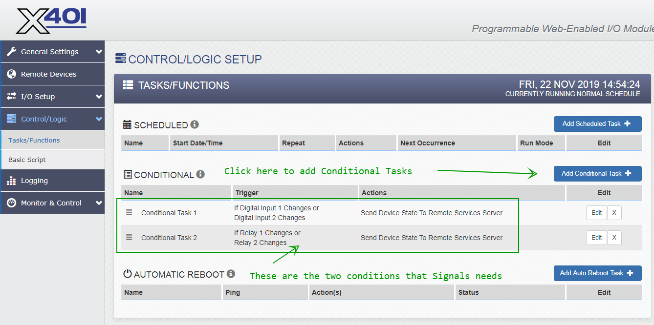
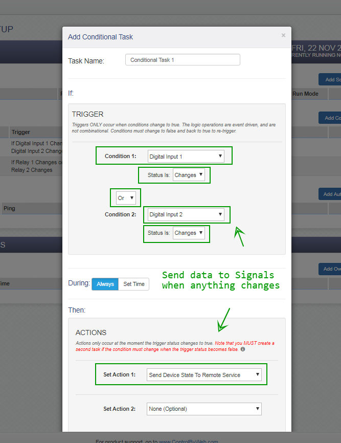
NOTE: The screenshots above include a conditional task to send data to Signals for relay state changes, but that is not strictly necessary.
The WebRelay-Dual (X-301) device provides its MAC address to ICON Signals and is used to create a unique device ID used within the application. For example:
SD303003F7A7
  SD = family  (StdDev)
  303 = type
  003F7A7 = 0 + last 6 digits of MAC
The WebRelay (X-WR-1R12) device doesn't provide the MAC and there is no easy and reliable means to obtain it across subnets. So, instead we create a device ID using the WebRelay device IP address.
WR110A81018C
  WR = family   (StdDev variant for WebRelay)
  11 = type     (1 input, 1 relay)
  0A81018C = 10.129.1.141 in hex
The obvious shortcoming of this approach is that the device ID will be different when the WebRelay's IP address is changed. However, this will be more of a lab and pre-installation nuisance than a problem for customers.
ICON Signals uses the Remote Services functionality of the WebRelay-Dual.
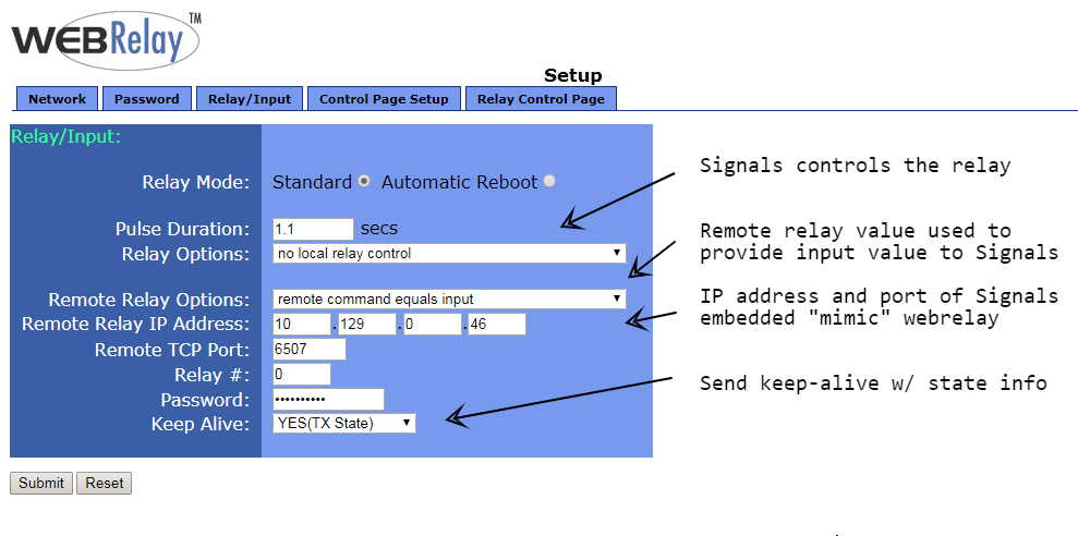
The WebRelay doesn't have Remote Services, so we use what can be described as a "Relay Masquerade" mode.
The WebRelay can be configured to send its input state to a remote webrelay device as shown above. If the ICON Signals server address and port are used as the remote webrelay device, Signals will obtain the input state of the device from the HTTP request info.
Note that in this configuration the input state and relay state of the device are independent from each other. For example, Signals might receive (contact closure) input state changes 24x7, but only turn on the device's relay during office hours on weekdays.
If the WebRelay is sending data to ICON Signals, then a new device will appear in the Sensor Grid.
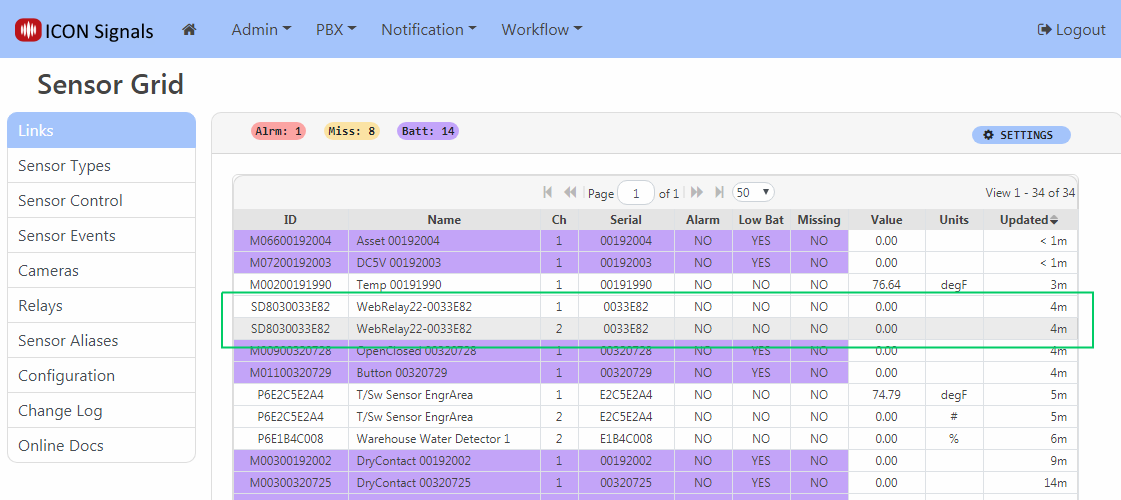
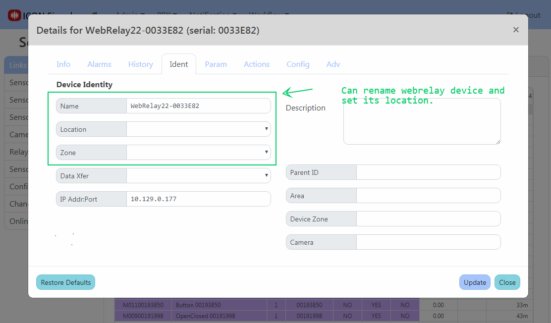
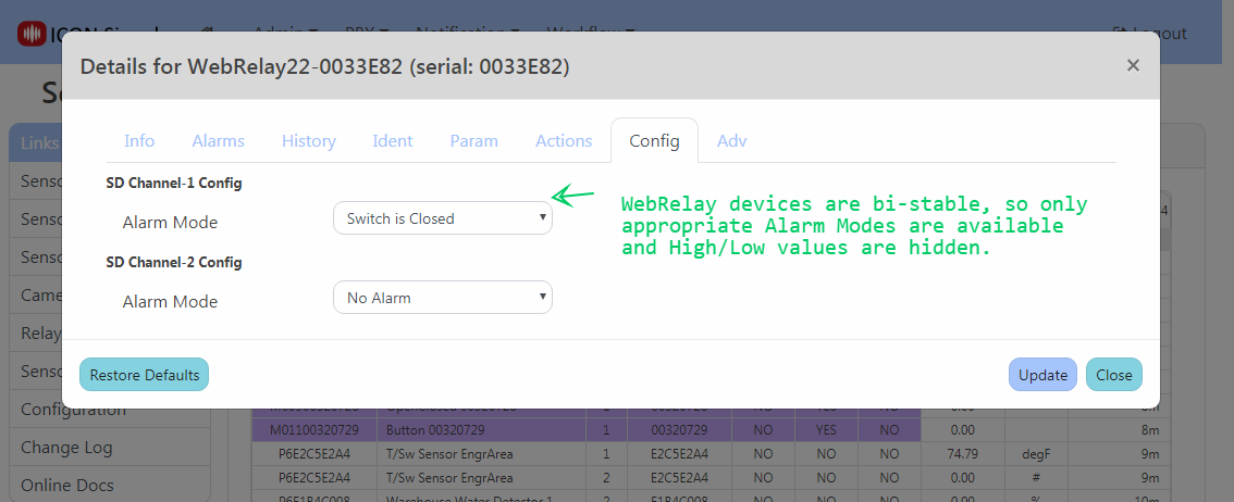
Click on the device to set name and location as well as to define which state(s) represent an alarm condition.
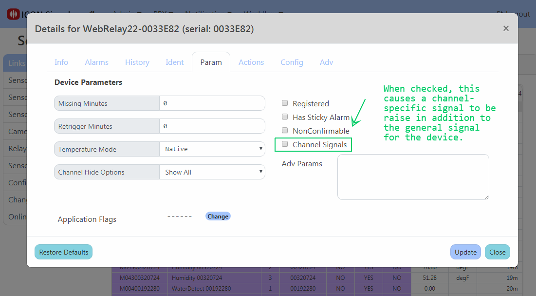
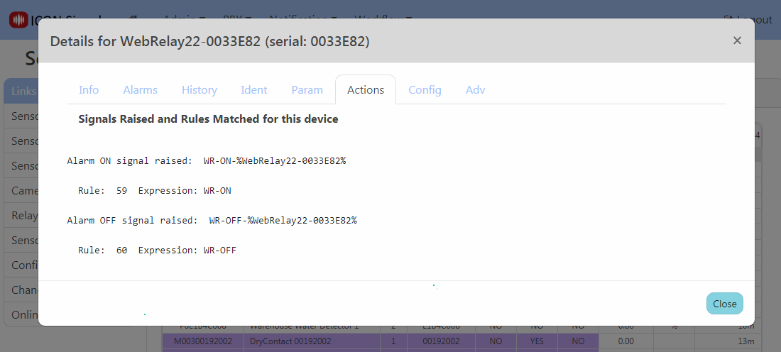
When the WebRelay device goes into an out of alarm state, ICON Signals raises the signals shown in the Actions tab. If we were using Web Relay devices to trigger a lockdown, we would likely create a rule with the expression WR-ON (which would match against all WebRelay devices) and redirect it to our LOCKDOWN rule.
The WebRelay device relays can be configured to mirror the associated input state. (e.g. Switch closes, relay turned on, stobe light is lit). But what if you need programmatic control of the relay? For example, the relay is not turned off until a lockdown command is received.
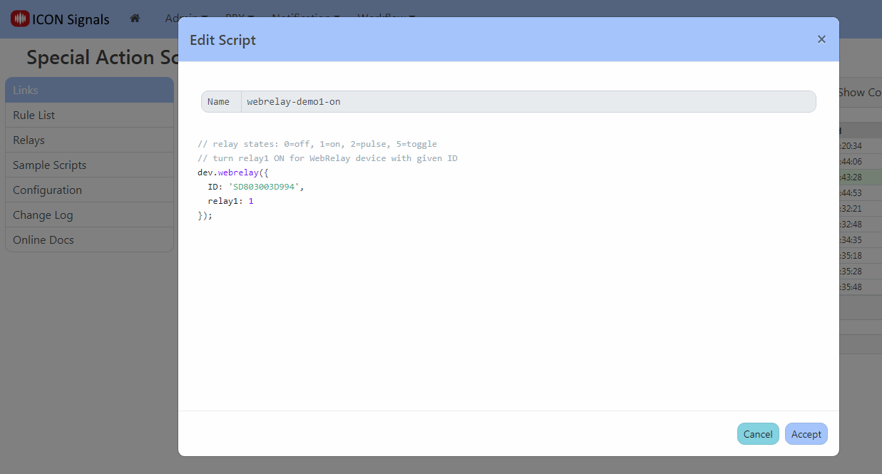
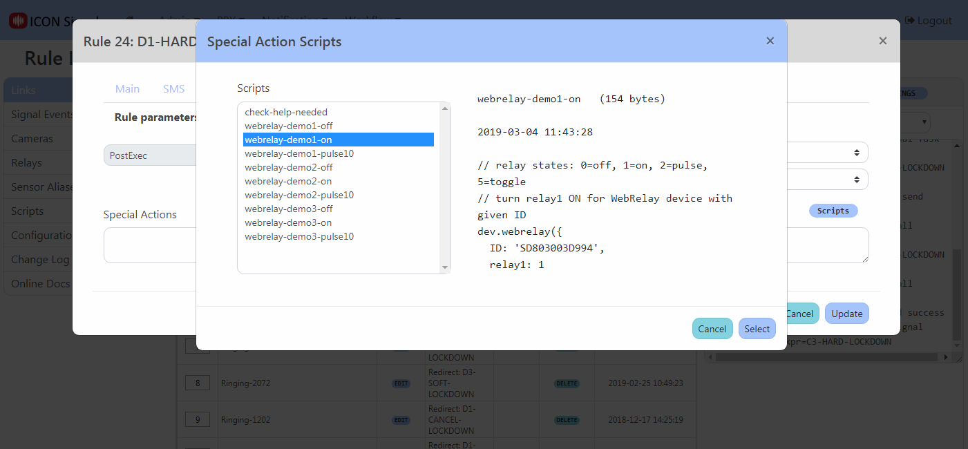
Special actions are very short scripts included in a rule to perform actions outside of what's available in the user interface.
In this case, a new signals script API function called stddev.webrelay() can be used to do anything allowed by the WebRelay device. The script can turn either relay on or off, toggle the value, or pulse a relay for a specified duration.
Example screenshots follow.
stddev.webrelay() parameters for WebRelay-Dual (X-301 and X-401)| ID | Device ID |
|---|---|
| relay1 | 0=off, 1=on, 2=pulse, 5=toggle |
| pulse1 | pulse time (secs) for relay 1 in pulse mode |
| relay2 | 0=off, 1=on, 2=pulse, 5=toggle |
| pulse2 | pulse time (secs) for relay 2 in pulse mode |
If a pulse duration is not provided as a parameter, the device uses its configured default value.
stddev.webrelay() parameters for WebRelay (X-WR-1R12)| ID | Device ID |
|---|---|
| relay | 0=off, 1=on, 2=pulse, 5=toggle |
Unlike the X-301, pulse duration can only be configured in the device itself.
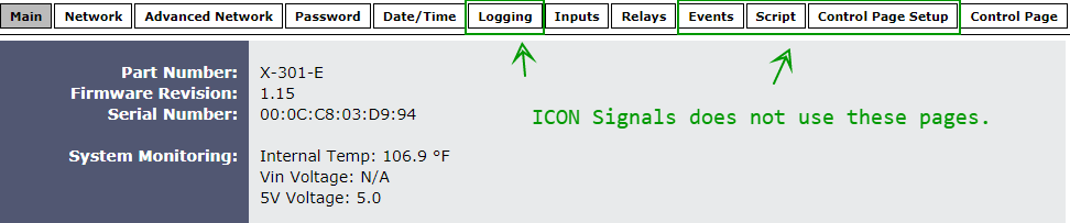
Follow X-301 Quick Start Guide to set up Network. Then browse to {ip_addr}/setup.html
Network
Advanced Network
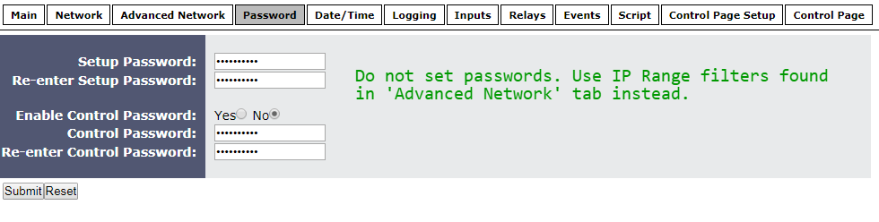
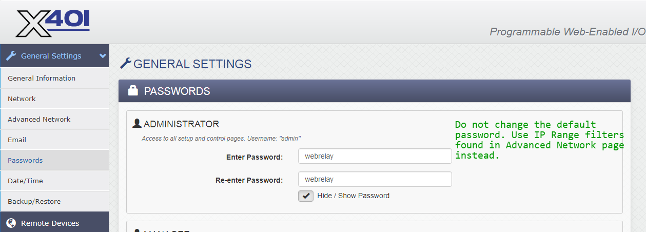
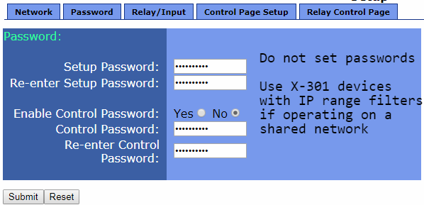
Password
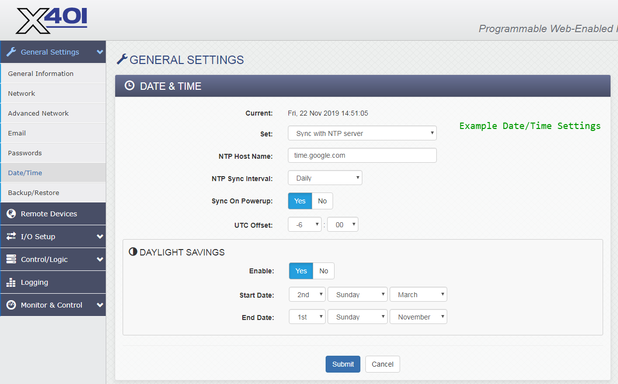
Date / Time
Logging
Inputs
Relays
Events, Script, Control Page Setup
Follow X-WR-1R12 Quick Start Guide to set up Network.
Then browse to {ip_addr}/setup.html
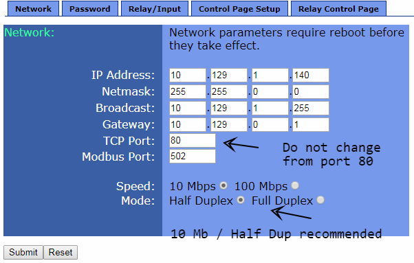
Network
Password
Relay / Input
Control Page Setup
                  +----------------+
                  |                |
                  +                |
         o+------+o Vout           |
Contact 1           Gnd  o+----+   |
         o+------+o In1+       |   |
                    In1- o+----+   |
                               |   |
         o+------+o In2+       |   |
Contact 2           In2- o+----+   |
         o+--+                     |
             +---------------------+
 V IN+
 V IN-  o+---+
             |
 INPUT- o+---+
 INPUT+ o+-------+o
                   Contact
+5V OUT o+-------+o
2018-2022 ICON Voice Networks