| date | desc |
|---|---|
| 19 Jul 2021 | initial |
| 15 Dec 2022 | added ideas about detecting missing input power |
This document details configuration and operation of the ControlByWeb WebRelay X-408 device for contact sensing by ICON Signals. The X-408 has 8 optically-isolated digital inputs and no relays.
Important Notes!
ICON Signals has no visibility into how WebRelay devices are configured and assumes they are set up as described in this document.
The non-PoE versions of these devices will work with ICON Signals, but the circuit diagrams may be slightly different.
Other WebRelay products will not work with ICON Signals until we write software to support them.
This document will include screenshots of the WebRelay interfaces when discussing their use within ICON Signals, but will not describe all features of those products.
Product documentation is available at: https://www.controlbyweb.com
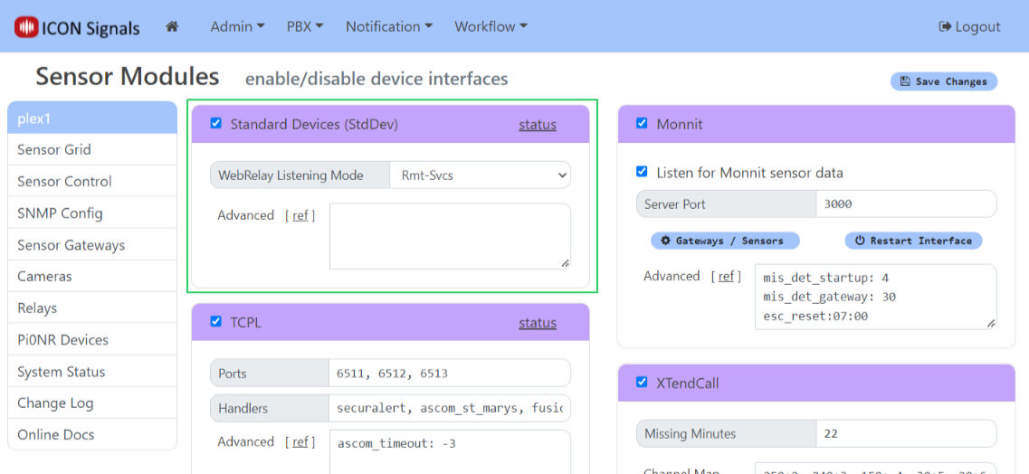
ICON Signals supports different families of sensor devices, each of which can be enabled or disabled in the Workflow > Sensor Modules page. The Standard Device Interface is used for devices which are not directly configured by ICON Signals itself. Examples include passive environmental sensors, webcams, and other devices which are configured outside of ICON Signals and which simply send data to ICON Signals.
ControlByWeb devices are handled within the Standard Device Interface. When this interface is enabled, Signals does the following with respect to webrelay devices:
(Note: Changing the Remote Services port from 6506 to another value is not recommended and should only be done in consultation with ICON support.)
WebRelay devices that do not have Remote Services (e.g. the 1-input, 1-relay WebRelay X-WR-1R12) do not use the WebRelay listener.
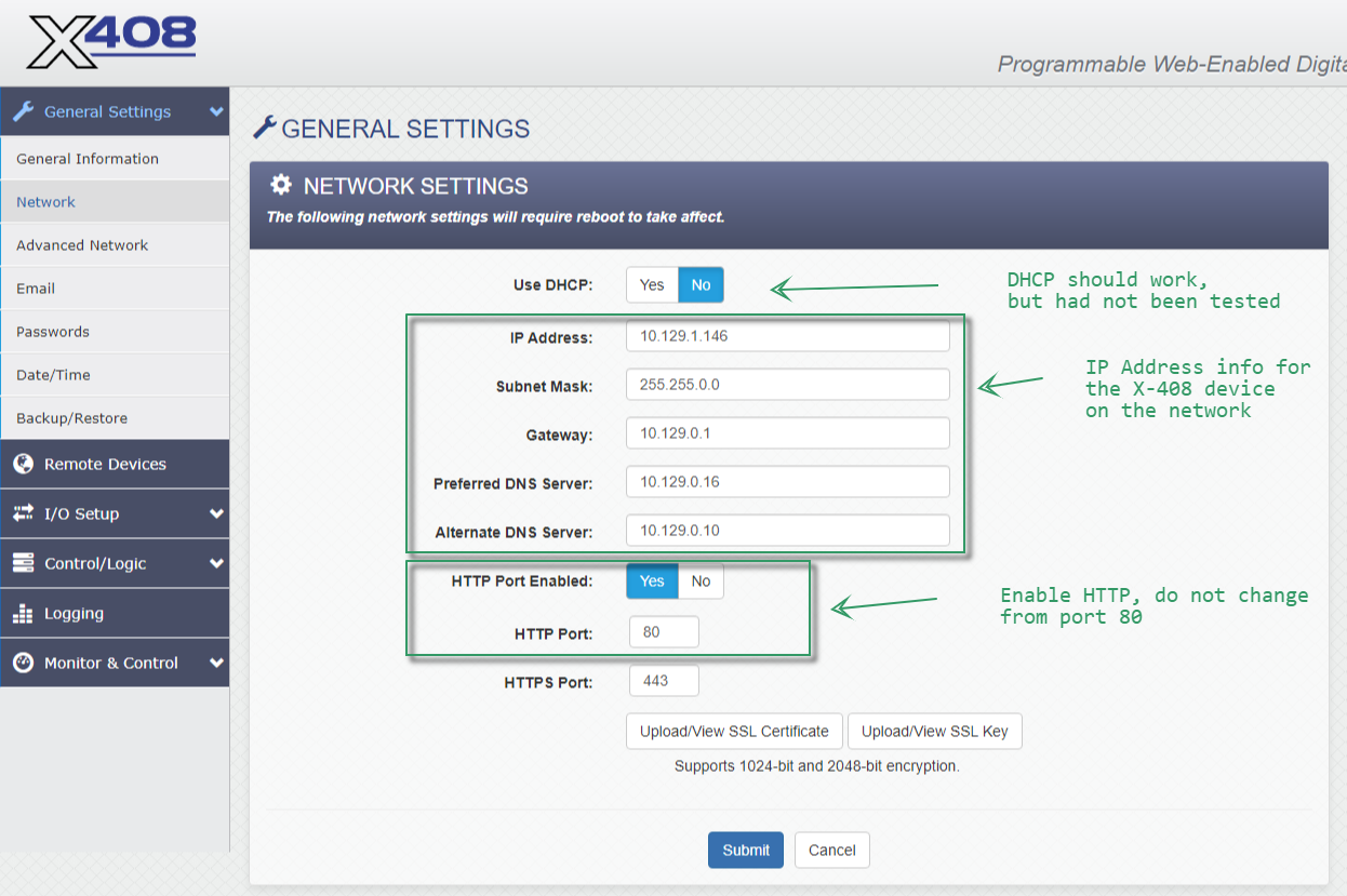
Configure the WebRelay device to be on the same network as the ICON Signals server. Refer to the manual for details.
For all ControlByWeb devices,
{ip-address}/setup.htmladmin and password is webrelayFollow the "Quick-Start Guide" shipped with the X-400 to get it on the same network as the ICON Signals server. Then continue reading this section.
For sites using more than one X-408:
After completely setting up one X-408 and having it work with ICON Signals, you can export the settings file and use it to set up other X-408 devices for the site. This procedure is covered in Section 6.
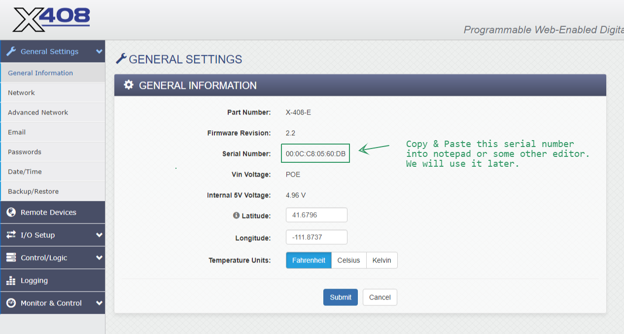
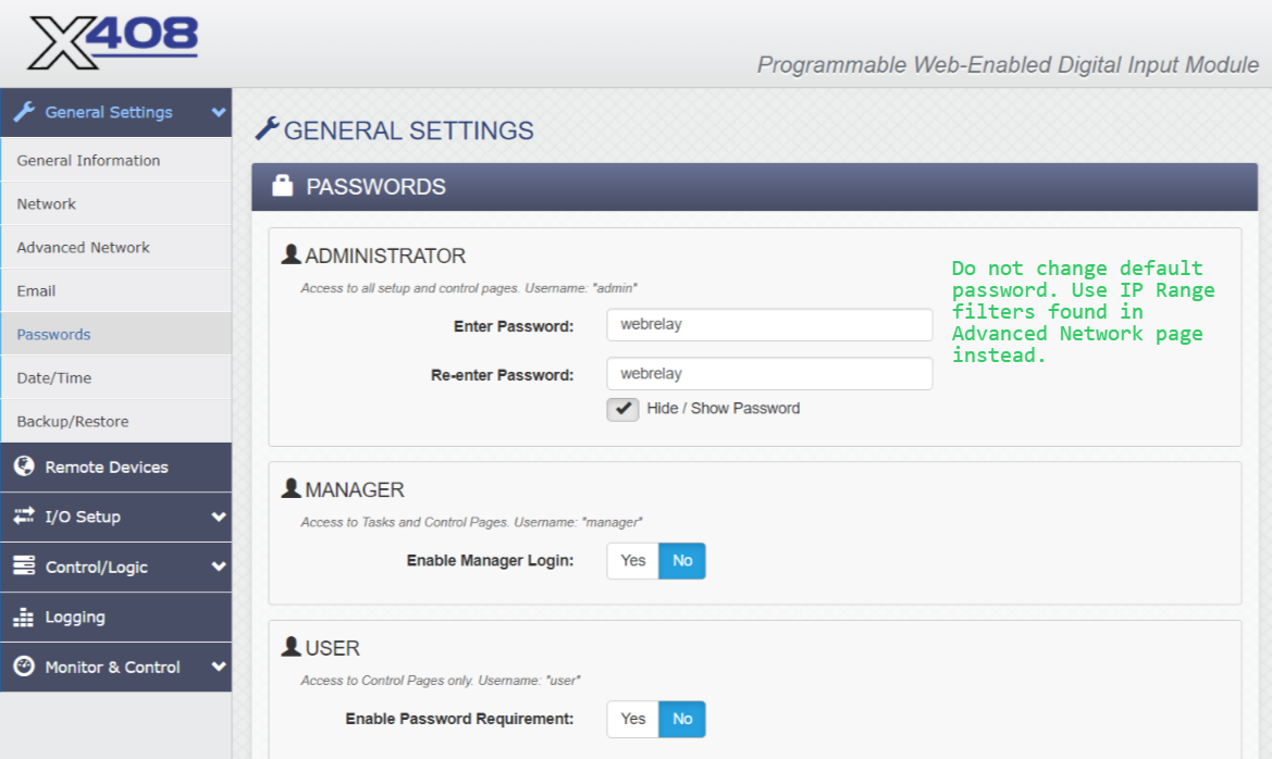
Screenshots from the WebRelay setup pages follow with relevant comments.
The screenshots below show the changes needed to work with Signals.
When making any changes, you must click the Submit button at the bottom of the page.
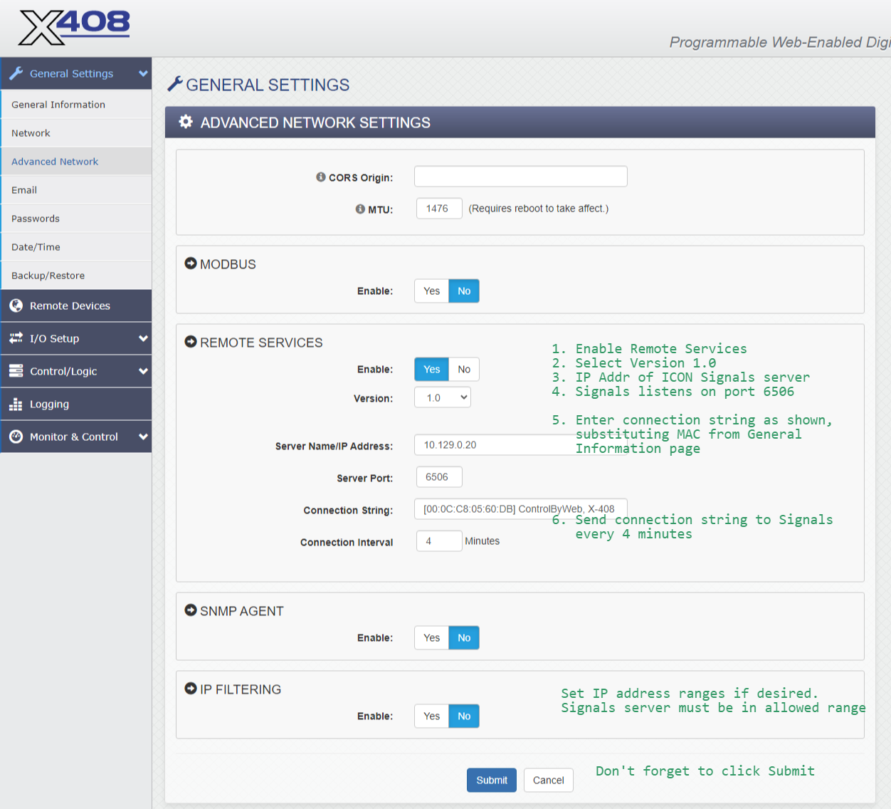
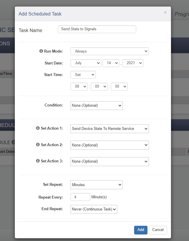
When Remote Services is enabled, the WebRelay makes a TCP connection to the given IP address and port and sends the connection string. After that it periodically sends the connection string to the destination server. ICON Signals expects to find the MAC address in the connection string, so please configure it as shown in the above screenshot.
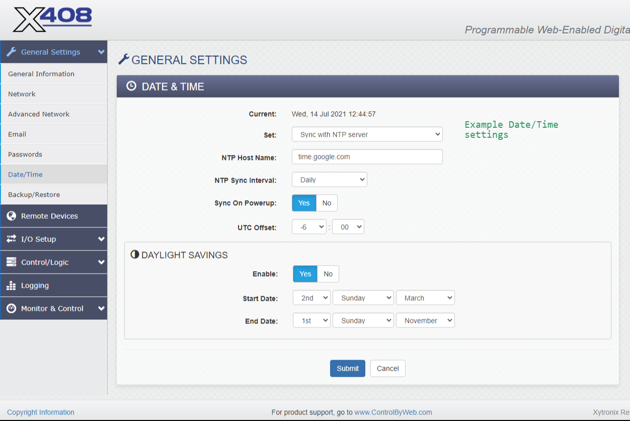
No changes needed to this page or to the Email page.
Date & Time settings are important because the Control/Logic configuration makes use of them. Sync with an NTP server on a fairly frequent basis (e.g. once a day).
No changes are needed in the next two major sections of the left navigation: Remote Devices and I/O Setup.
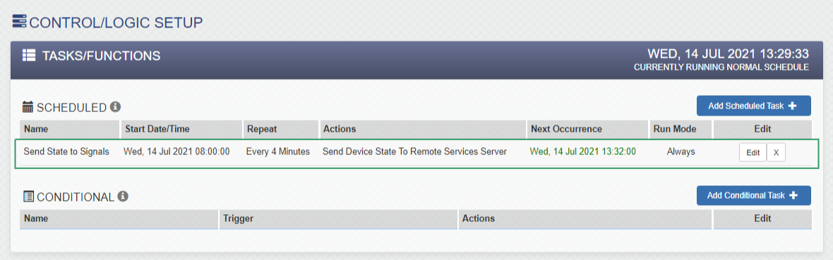
The Control/Logic Setup > Tasks/Functions page is critical to the integration with ICON Signals. Basically we configure the X-408 to send state information every few minutes or when anything changes. One or more rules within Signals will determine what happens next. For example, a rule might only perform an action when Digital Input 1 is turned ON.
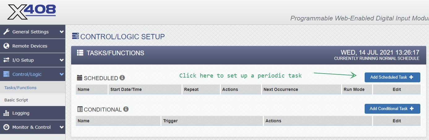
Create a scheduled task to send the device state to Signals every few minutes via Remote Services. (See screenshots below.)
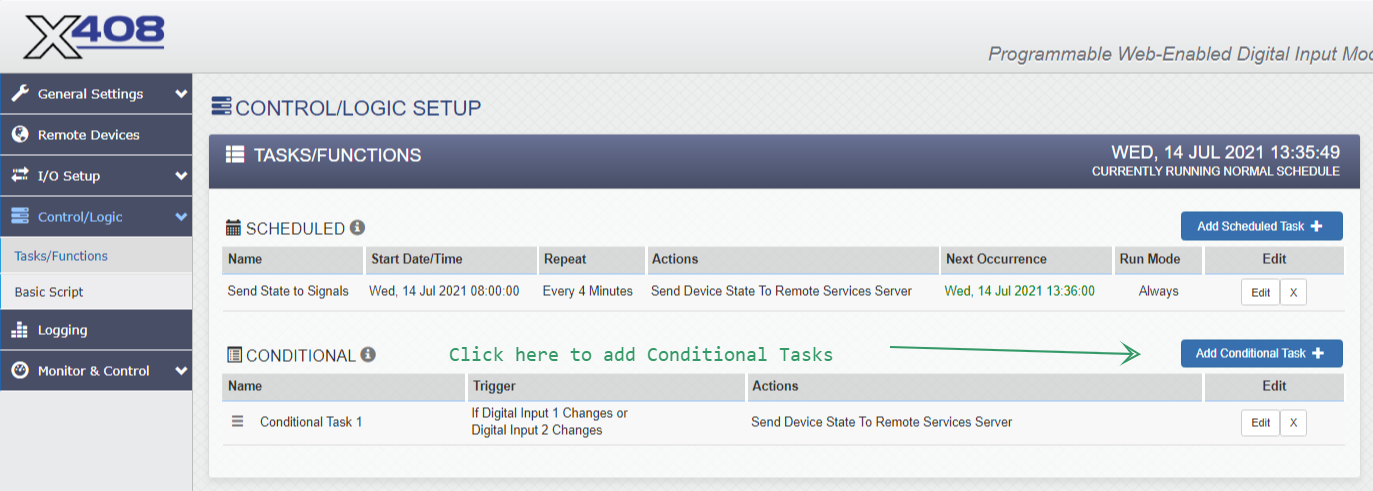
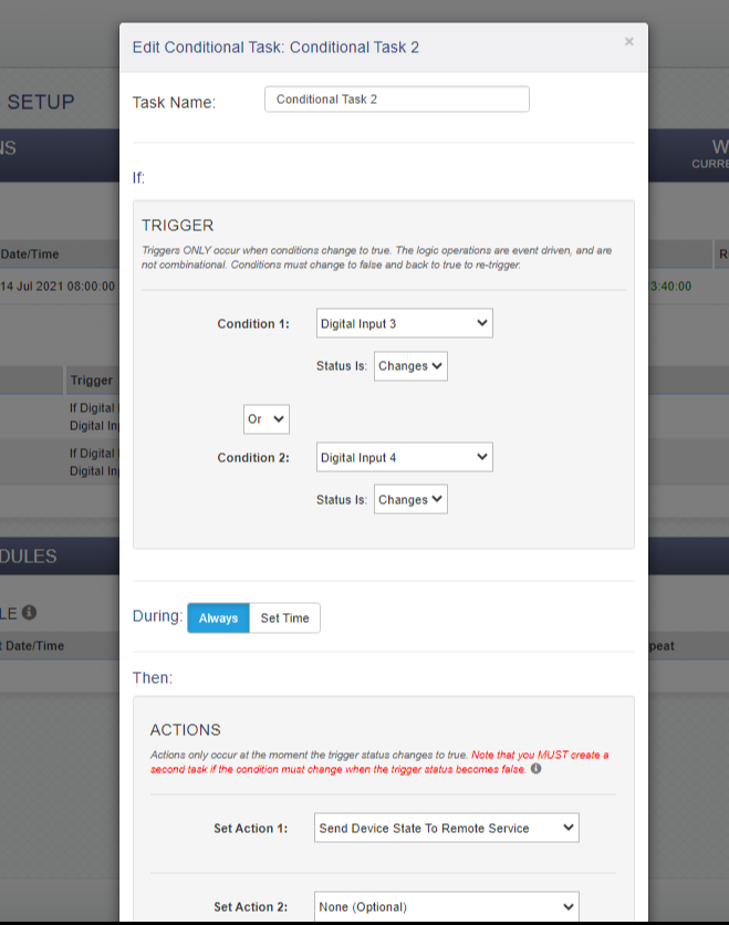
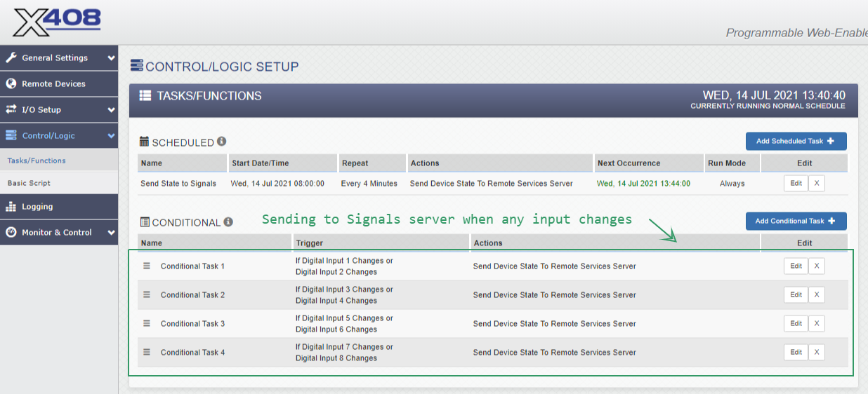
As previously mentioned, we want to send device state to Signals whenever a digital input state changes. Each Conditional Task allows us to configure this for two inputs. (See screenshots below.)
No changes are needed in the last two major sections of the left navigation: Logging and Monitor & Control. However, the Monitor & Control > Control Page can be useful when initially setting up and verifying contact closure wiring.
When ICON Signals receives data for an unknown WebRelay device, it creates entries in the database for that device and all of its I/O channels. For an X-408, that results in a Workflow > Sensor Grid device with 8 rows of I/O data channels.
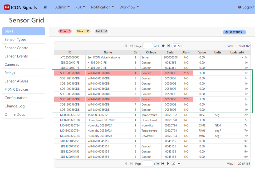
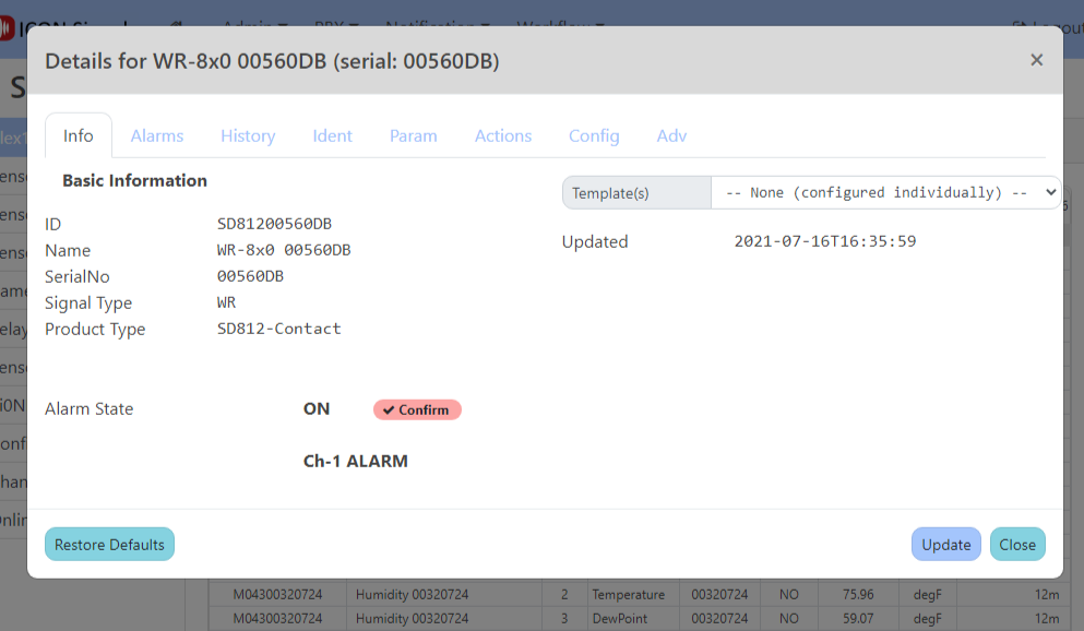
Click on any of the grid rows for the X-408 to open the device dialog.
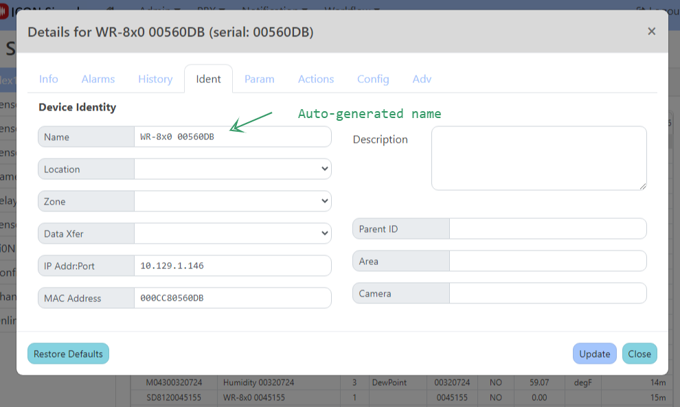
In the Ident tab, you may change the name of the device to something meaningful for the project. We typically create rules which match against the device name - especially if there are multiple webrelay devices at the site.
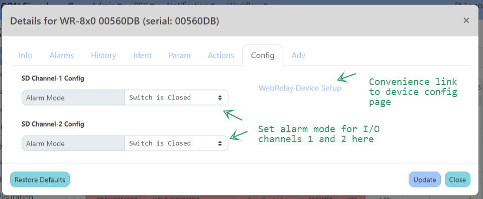
In the Config tab, we set the alarm mode for the first two I/O channels. In the Param tab, we check the Channel Signals box and set an Advanced parameter.
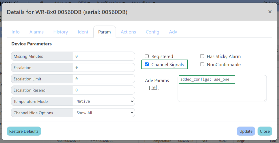
Within ICON Signals, every device enters alarm state and an ON signal is raised whenever any of its inputs enters alarm state. The device leaves alarm state and an OFF signal is raised when all of the inputs leave alarm state.
This is not helpful for a device with multiple I/O channels when we want to monitor those channels independently. That's where Channel Signals come in. When enabled, ICON Signals will raise ON and OFF signals for each individual channel as it enters and exits alarm state.
The advanced parameter added_configs: use_one means that I/O channels 3 thru 8 will use the alarm mode configuration for channel 1.
Special Note:
The X-408 requires an external power supply for the digital inputs. This includes the PoE version of the device. ControlByWeb sells the part PS12VW1.5-B for this purpose. (ICON partno: 104864).
For a project using normally-open (NO) inputs, "no-alarm" state information looks similar to state information received when the input power supply is missing or disconnected.
For that reason, we recommend wiring I/O channel 2 as a normally-closed (NC) input and writing a rule in Signals to detect when channel 2 is open - which would indicate the input power supply is not connected.
The state information also includes the input voltage. In the future we may implement code to detect the diconnected-power condition based on that value.
When a WebRelay device or I/O channel enters or exits alarm state, ICON Signals raises signals with the following names:
| event | signame |
|---|---|
| device enters alarm state (at least one channel in alarm state) | WR-ON-%{device name}% |
| I/O channel enters alarm state for a device w/ Channel Signals enabled | WR-ON-CH{nbr}-%{device name}% |
| device exits alarm state (last alarm state channel leaves alarm state) | WR-OFF-%{device name}% |
| I/O channel exits alarm state for a device w/ Channel Signals enabled | WR-OFF-CH{nbr}-%{device name}% |
Example signal names for the device shown in previous screenshots are:
  WR-ON-%WR-8x0 00560DB%
  WR-OFF-%WR-8x0 00560DB%
  WR-OFF-CH1-%WR-8x0 00560DB%
  WR-ON-CH6-%WR-8x0 00560DB%
For some devices it is desirable to write separate rules for each I/O channel to perform different actions.
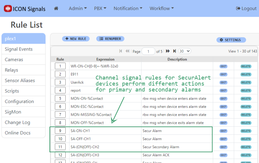
For a device with a large number of inputs, it is usually better to have a small number of channel rules (maybe just one) which match against multiple channel signals.
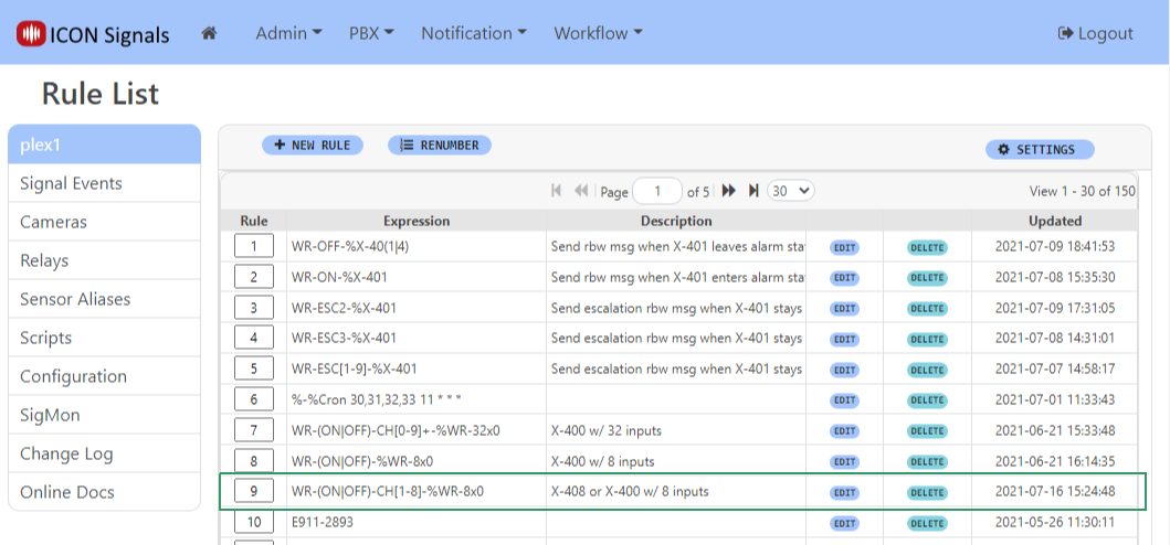
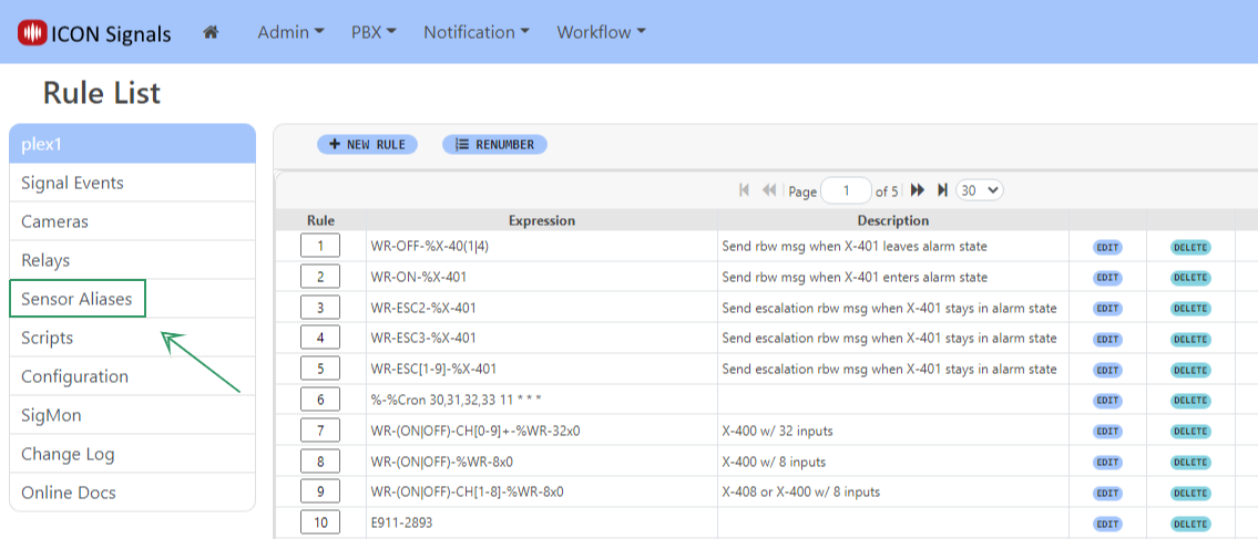
Regular Expression matching is used. Rule 9 in the above rule list will match with an ON or OFF channel signal for any WebRelay device with a name beginning with WR-8x0.
In this example, we will configure a rule to display a basic Rainbow message for X-408 contact closures.
When a signal is raised, the ICON Signals application searches the Rule List sequentially looking for a rule expression that matches the signal name.
If a match is found, the rule - which is essentially a script - is executed by the Signals Rule Engine.
Clicking on the Edit button for a rule in the Rule List displays the rule dialog.
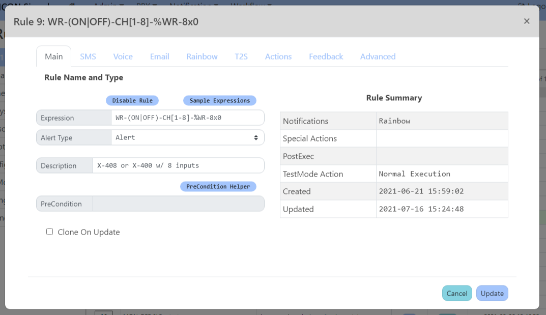
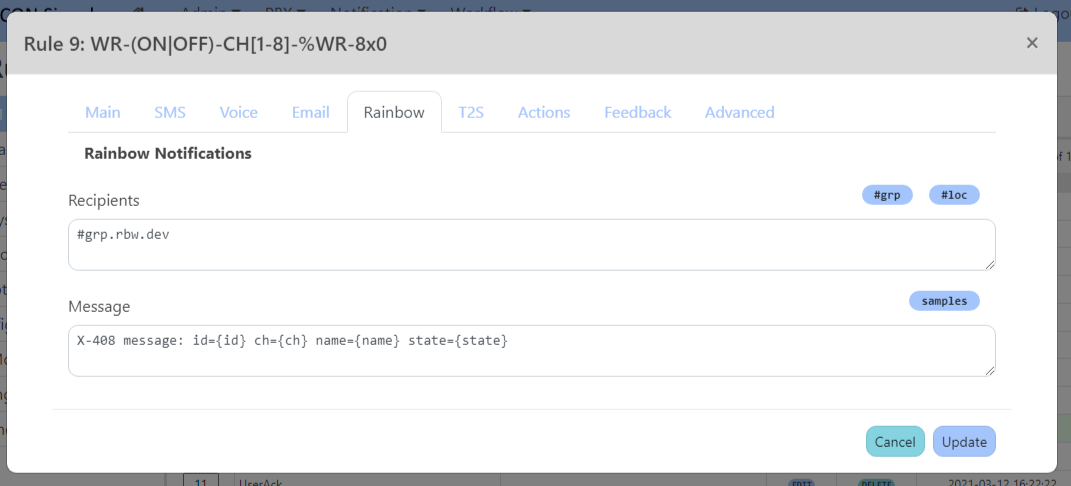
A contact closure on input 6 executes this rule and generates the following Rainbow message.

The {id}, {name} and {ch} tags were replaced with the Device ID, Device Name and Channel Number respectively.
We can replace the Device Name with a more useful sensor alias which describes that specific input. Click on the Sensor Aliases navigate link on the Rule List page.
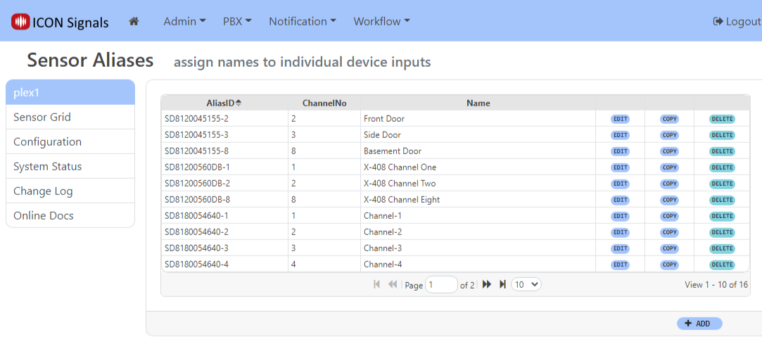
Click the ADD button to create a new alias for a given device id (in this case the X-408) and I/O channel.
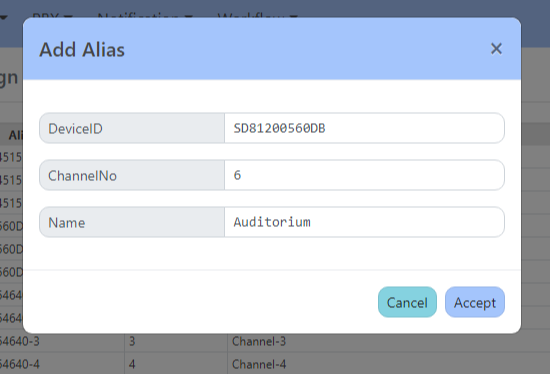
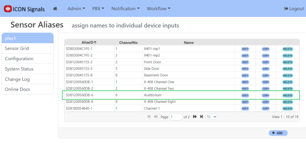
Note that after creating an alias for one channel of a device, you can click the COPY link to get an "Add Alias" dialog with pre-filled fields
Repeating the contact closure test for input 6 generates the following Rainbow message:

This example generates a Rainbow message, but the process also works for SMS and Email messages.
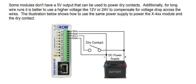
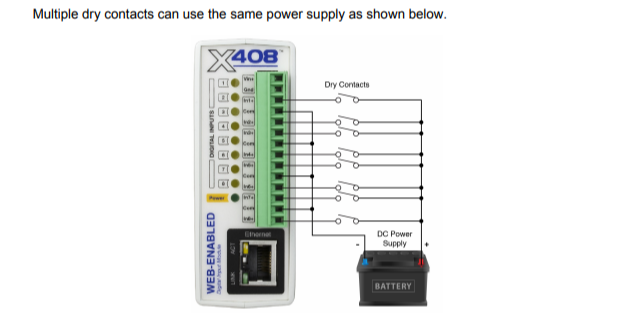
The following diagrams are copied from ControlByWeb's X-4xx Series User Manual.
NOTE: The X-408 does not have a 5V output that can be used to power dry contacts. An external power supply is required - even for the PoE version of the X-408 device.
Once configuration of the first X-408 is completed, settings for that device can be exported to a file in the General Settings > Backup/Restore page.
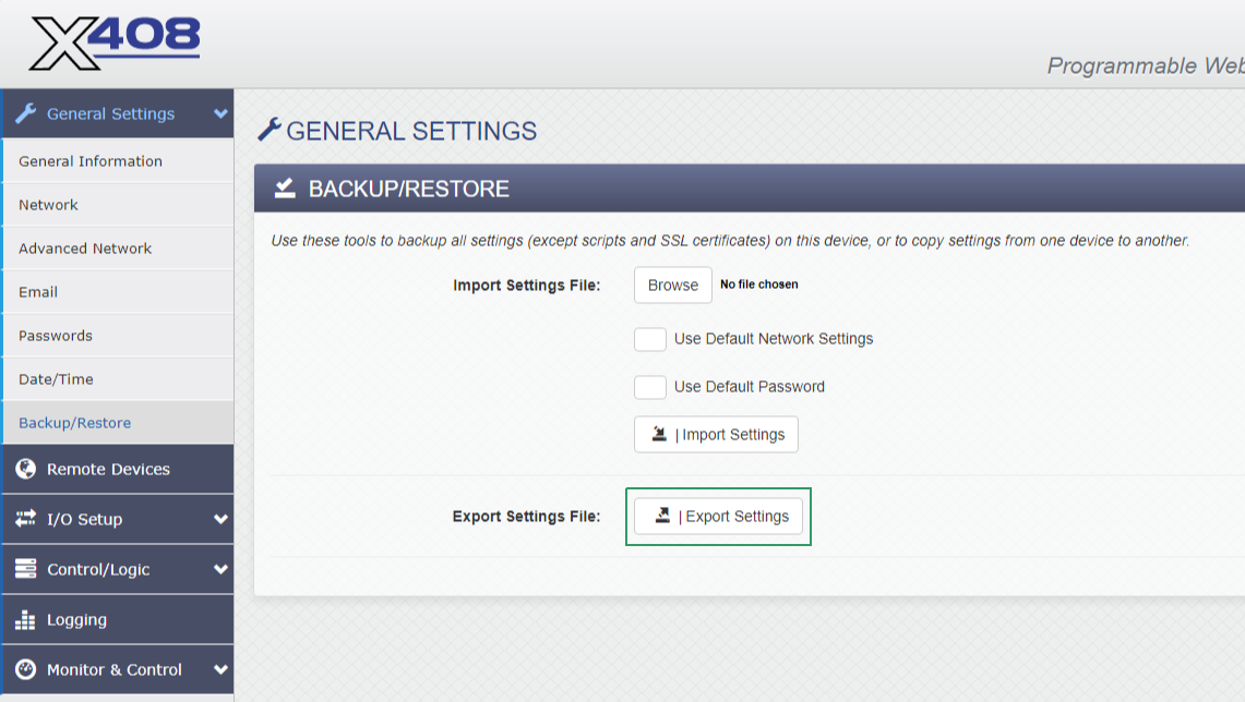
This file, settings.txt stored in the Downloads directory, can subsequently be imported into other X-408 devices during initial setup (when the IP address is 192.168.1.2).
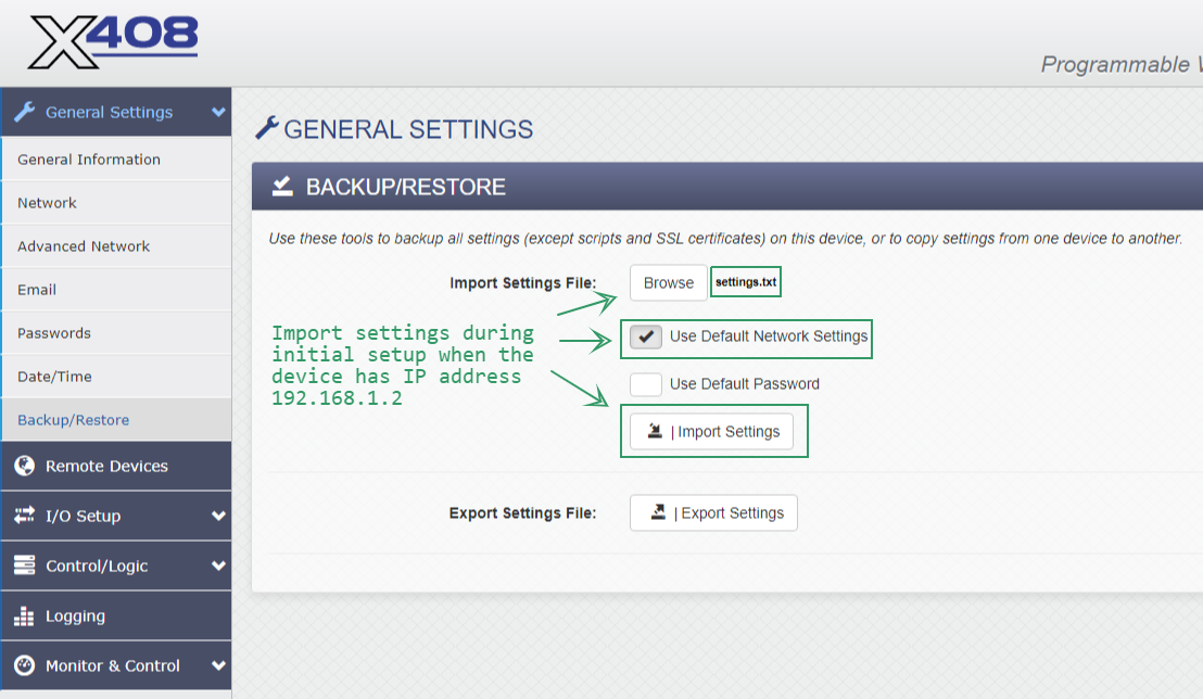
Once import is complete, you will need to perform some of the changes detailed in section 3.1.
General Settings > Network
General Settings > Advanced Network
It will be necessary to cycle power on the X-408 after making these changes. The new device should then appear in the ICON Signals Sensor Grid.
2018-2022 ICON Voice Networks