| date | desc |
|---|---|
| 29 May 2020 | initial |
| 10 Jun 2020 | added support for up to 3 sensors |
| 14 Apr 2023 | support for up to 16 sensors |
This note covers the ControlByWeb X-405 Temperature and Humidity Module.
The device can support multiple probes using the 1-Wire protocol.
Signals supports from 1 to 16 temperature probes per device. Support for humidity sensor probes may be added if we have customer interest.
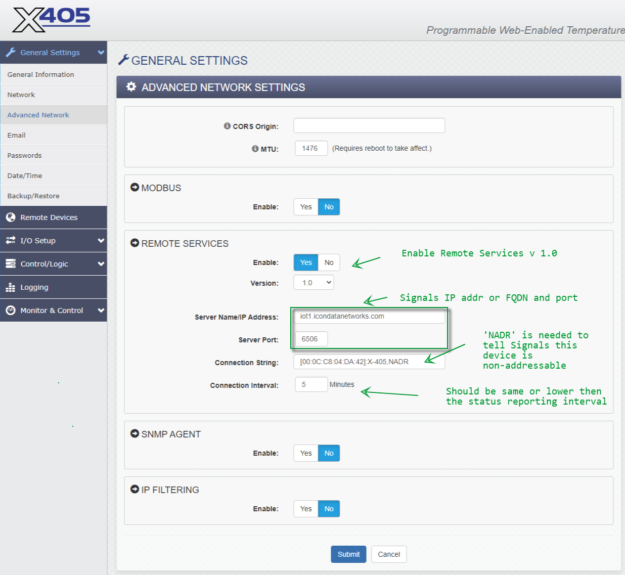
The initial application for this device was a cloud-based deployment. Consequently, some configuration details covered below will be for that case.
A key detail of cloud deployment is that Signals must be provided with the MAC address both in the connection string and in the data packet. We cannot use the IP address to identify devices because multiple devices on the client's network will share the same public IP address when data is sent to the cloud-based Signals server.
NOTE: The word "WebRelay" is used as a brand designator in this document - even for devices that have no relay outputs.
The following is taken from the X-405 manual.
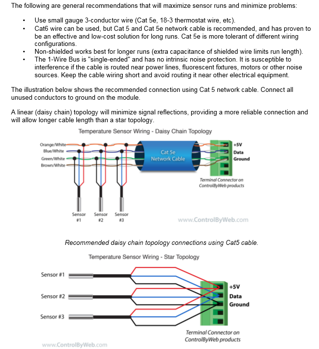
One-wire protocol sensors have a unique factory-generated Id. This allows them to be connected to a single data wire in a daisy-chain arrangement. In my work on the X-405, the conclusions I reached were:
Two sensors can be connected directly to the device's terminal connector with some care, but three is probably too many.
Daisy-chain connectivity using a Cat-5 cable as described in the X-405 manual is challenging due to the small size of the wires. Not recommended.
Wiring into a terminal block is probably the best approach.
The 1-Wire Bus protocol can support up to 16 sensors. ICON Signals can support all 16 sensors with some configuration limitations which will be discussed in this document.
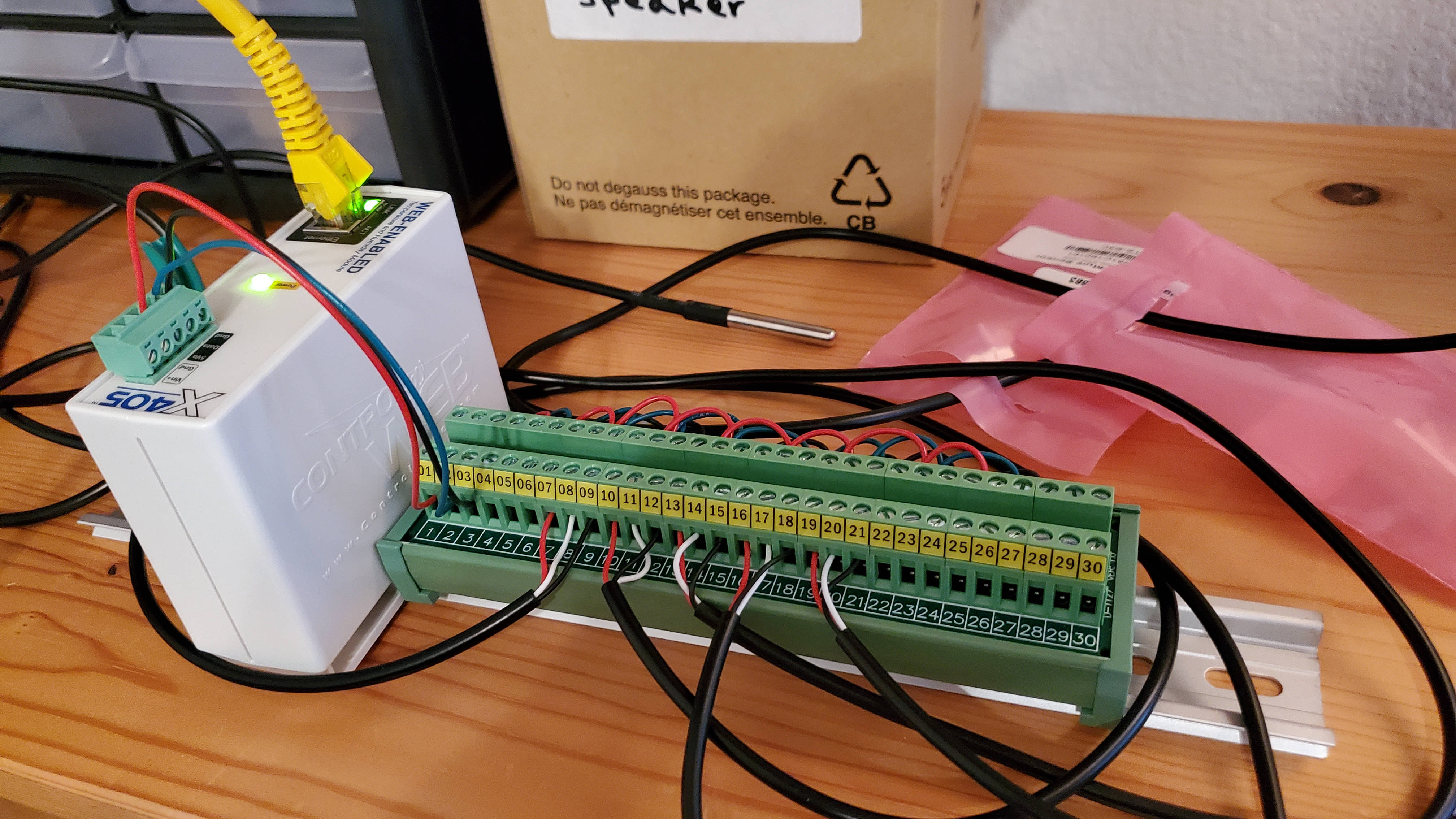
For longer cable runs, I would suggest using something like 18-gauge, 5-conductor thermostat wire.
Screenshots and comments are below. For this implementation we are setting temperature limits for the device for the purpose of pushing remote service data packets to Signals off schedule when a temperature reading goes out of range.
However, temperature limits configured in Signals itself are used to determine if the sensor is in alarm mode and initiate notification actions.
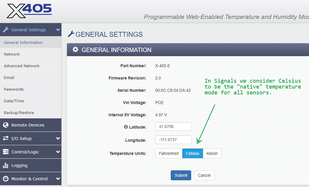
Most temperature sensors supported by Signals provide Celsius values, so we set the units to that scale. It is a bit of a nuisance when configuring the limits later in this document. Reporting in Signals will typically be done using the Fahrenheit scale.
We don't change anything in Email and Passwords pages.
Changes to Date/Time are optional. We typically use time.google.com as the NTP server and have it sync daily.
No changes to Backup/Restore.
No changes to this section.
ICON Signals adds a device to the Sensor Grid the first time it receives data for the device. The data message format and content, along with the transmission protocol, determine the device type and number of data channels (a.k.a. I/O channels).
Unlike other devices, the X-405 supports a variable number of sensors (data channels) via the 1-Wire Bus.
For 1 to 3 sensors, Signals can determine the number of I/O channels based on the data it receives.
For 4 or more sensors, we must configure a "register" variable to tell Signals how many inputs to expect.
If the number of inputs changes, it will be necessary to delete the X-405 device in the Signals Sensor Grid and allow it to be re-created when the next data is received with the desired final input configuration.
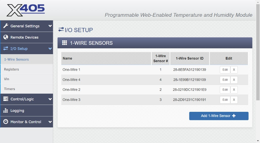
(3.3.1) 1-WIRE SENSORS
This is where we add the temperature probe(s). 1-Wire sensors have a factory-generated ID, so if a probe is replaced, you will need to edit the sensor configuration in this page.
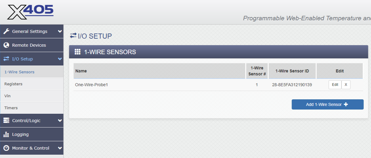
The configured Name value isn't sent to Signals. Sensors show up in the data as 'oneWireSensor1', 'oneWireSensor2', etc. I recommend using the default values, but if you want to rename them you can.
(3.3.2) Registers
We configure Register 1 as an Initial Value register to indicate the desired number of configured sensors. Supported values are listed in the following table.
| sensorType | number of sensors |
|---|---|
| 841 | 1 |
| 842 | 2 |
| 843 | 3 |
| 845 | 5 |
| 846 | 8 |
| 847 | 12 |
| 848 | 16 |
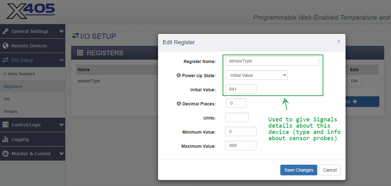
In this example we have renamed Register 1 as sensorTypes for visual clarity.
After setting or changing the Register 1 value, it is necessary to cycle power on the X-405 in order for the change to be recognized and sent to Signals in subsequent messages.
(3.3.3) Vin and Timers
No changes to the Vin or Timers pages.
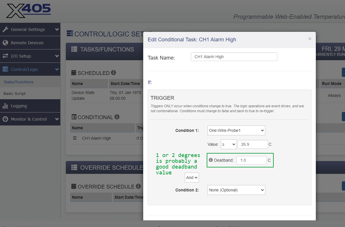
Tasks/Functions is the only page we configure in the Control/Logic section.
With regard to setting temperature limits in Celsius: subtract 32 from the desired Fahrenheit temperature, then multiply by 5, then divide by 9.
Celsius_Temp = (Fahrenheit_Temp - 32) * 5 / 9
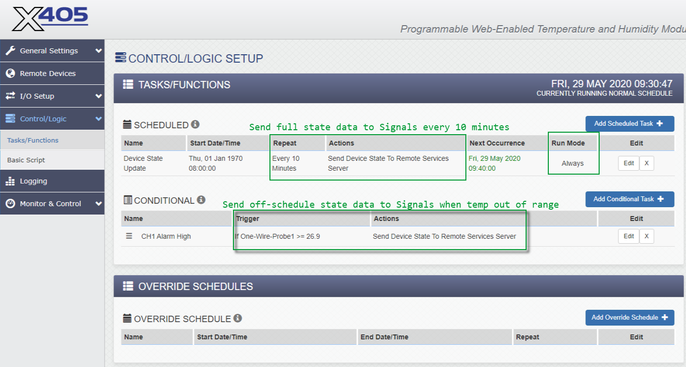
Setting a conditional task is optional, but if you do it we recommend a deadband value higher than zero.
This can prevent extraneous status reporting when a sensor value is fluctuating near the threshold value.
We don't change any other pages in this section.
No changes to this section.
We don't normally make changes to this section, but setting up a Control Page can be useful during testing.
ICON Signals was designed to support devices with one or two data channels. We have added support for devices with many more inputs, but there are some inevitable limitations.
Either Channel 1 or channel 2 config properties are used, as determined by an Advanced Parameters setting.
Signals maintains a 64-bit alarm state value for each device. The bits and bit fields are designed to support a large number of binary (i.e. contact closure) channels for the device. The design also supports high and low alarm bits for channels 1-14, but channels 15 and 16 share the same bit.
This isn't an issue for X-405 uses where we are only concerned with temperatures that are too high. But for applications such as vaccine refrigerators or freezers which must maintain temperatures in a specific range, a maximum of 14 temperature probes can be supported for a single X-405 device.
The following figures show WebRelay screenshots for a configuration with 5 sensor probes.
(4.1.1) 1-Wire Sensors
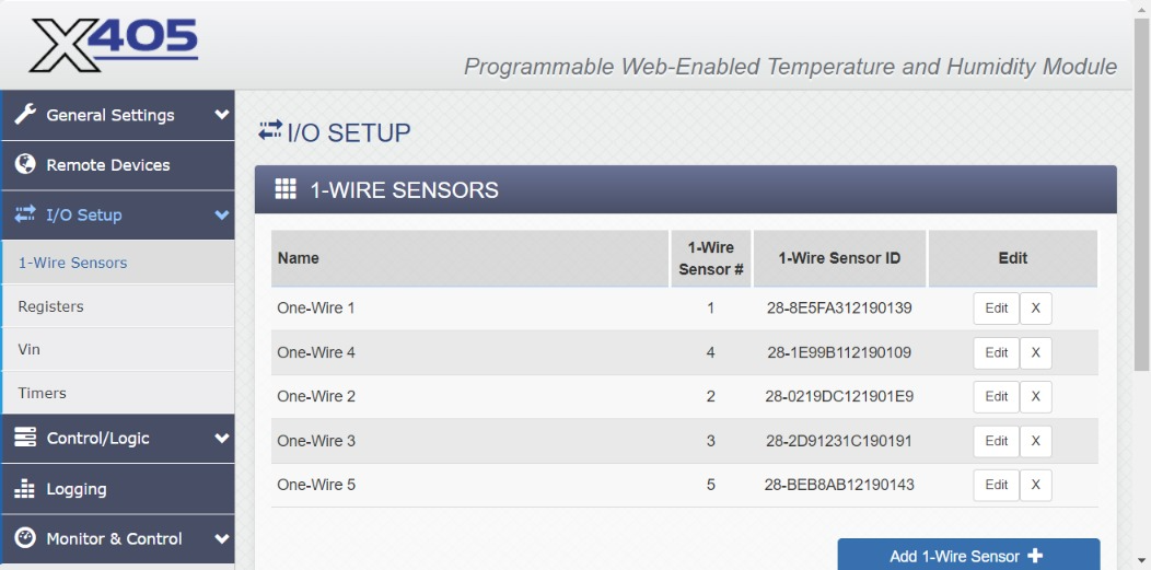
Currently configured with 4 probes.
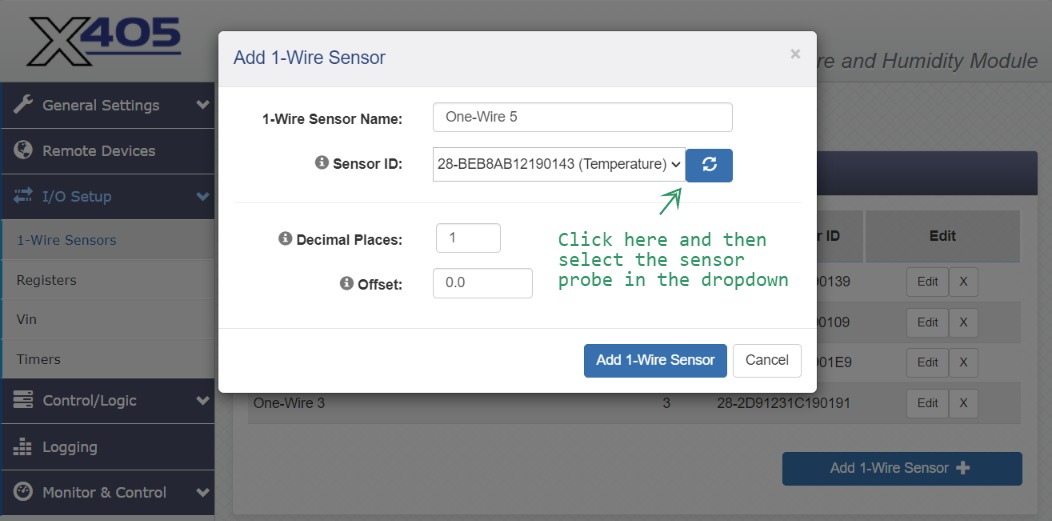
Now add a fifth sensor probe.
(4.1.2) Registers
As discussed in 3.3.2, Register 1 must be configured with an initial value of 846.
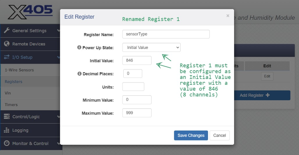
NOTE: After changing this value it will be necessary to cycle power to the X-405 by disconnecting and reconnecting the network cable.
The following figures show ICON Signals screenshots for the same 5-probe configuration.
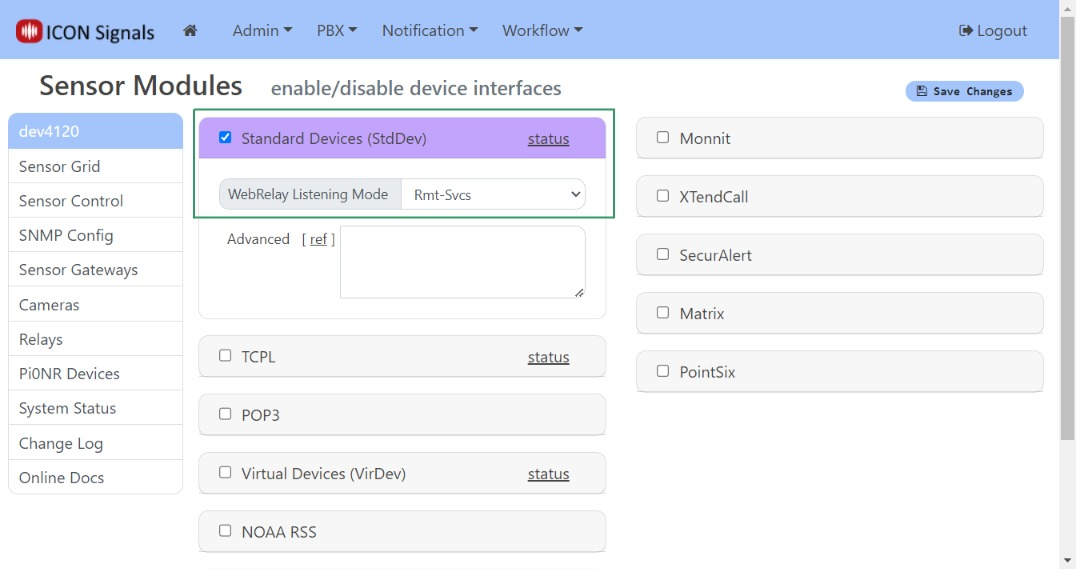
(4.2.1) Workflow > Sensor Modules
Enable the Standard Devices interface in Workflow > Sensor Modules
Set the WebRelay listening mode to Rmt-Svcs
(4.2.2) Workflow > Sensor Grid
As mentioned in 3.3, if Signals created a Sensor Grid entry for the X-405 with the "wrong" number of data channels, it is necessary to delete the device as shown below.
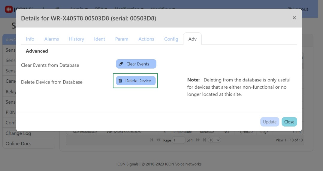
The device entry, along with the correct number of data channels, should be created again when the next data message is received from the X-405.
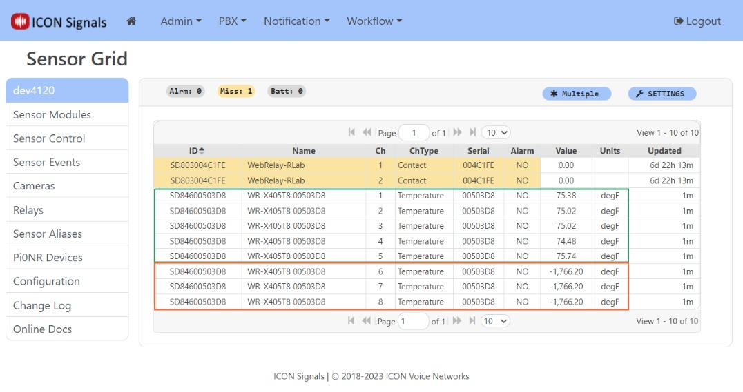
Channels 1-5 show data for the 5 temperature probes. Channels 6-8 show invalid values and can be ignored.
(4.2.3) Sensor Grid: Device Dialog
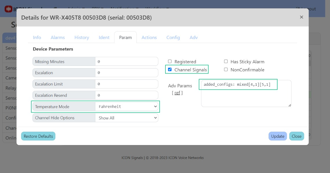
Clicking on any rows for the X-405 device opens the device dialog.
The Config tab is where we set the alarm mode and temperature range values for channels 1 and 2.
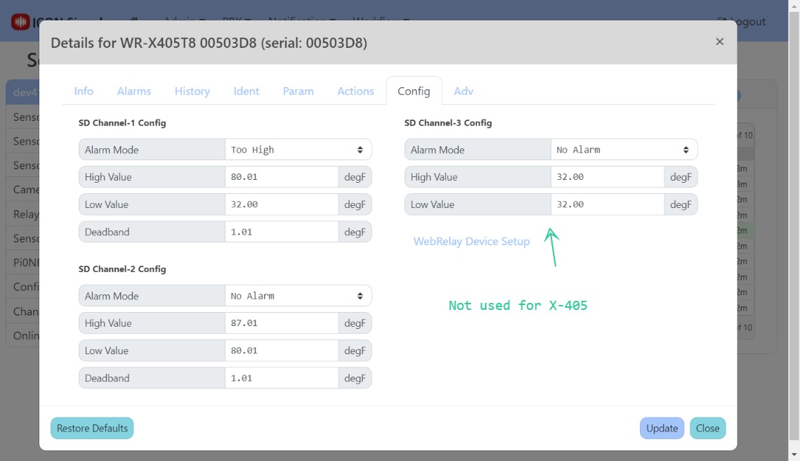
Other data channels use either the channel 1 or channel 2 settings - as determined by the Advanced Parameters field in the Param tab.
Set Temperature Mode to Fahrenheit if desired
Enable Channel Signals if the X-405 has more than one sensor probe
In Adv Params set an added_configs property to determine which temperature config setting is used for higher data channels
(4.2.4) Workflow > Rule List
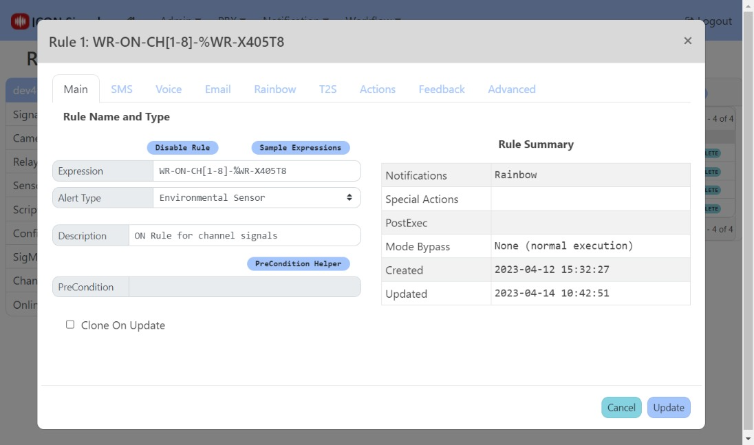
In ICON Signals, a device enters alarm state when any of its inputs enters alarm state and the device leaves alarm state when all of its inputs are no longer in alarm state.
Since the X-405 device has multiple probes, we are interested in matching against "Channel Signals". In other words we are interested in the alarm state of individual probes rather than the overall alarm state of the X-405 device itself.
A couple of channel signal rules are shown in the screenshot below.
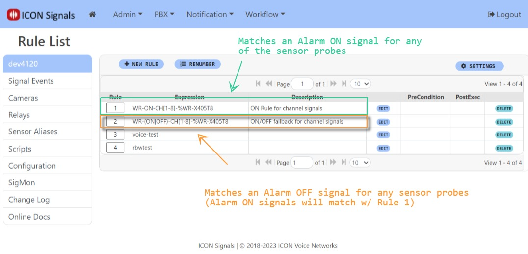
Rule 1 will be executed when any of the sensor probes enter alarm state.
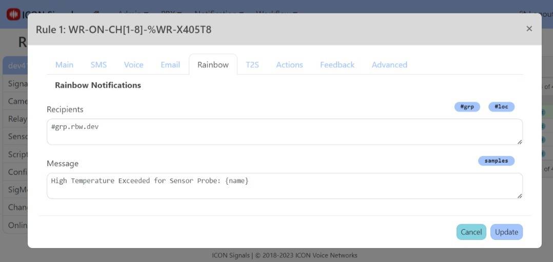

We can assign names to the sensor probes in the Sensor Aliases page. A link to it is on the left side of the Rules List page.

(Some of these side-comments are obsolete, but retained here for posterity.)
For most WebRelay devices we use Remote Services to communicate with the Signals server. So far we have seen many variations in implementation which had to be addressed. I will try to list them below.
No Remote Services support (X-WR-1R12)
We had to scrape a web page to get the MAC.
Connection string sent periodically, but data packet only on state change (X-301 and others)
When the Signals server starts, we need to either query the device to obtain its full state or have that state sent to us periodically. In a cloud environment, we cannot query the device.
Remote Services data packet not sent on state change (X-400)
This was a bug we discovered in the X-400 firmware. It would send the data packet only on the very first state change after device startup. This was presumably fixed but has not been re-tested. We did an elaborate work-around documented in the X-400 technote.
Remote Services data packet provides no serial number (i.e. MAC) (XW-111)
This is a characteristic of the stand-along mode of the wireless digital input sensor. It means the device cannot be used in the cloud deployment in standalone. However, the XCD format packet used in slave mode does contain the MAC and can be used in a cloud deployment. This is the preferred mode for a battery-powered device anyway.
2018-2023 ICON Voice Networks