| date | desc |
|---|---|
| 17 Apr 2019 | initial |
| 19 May 2021 | FW upgrade, support for up to 32 contacts |
This document covers the WebRelay X-400 and associated expansion modules.
It is an addendum to a a previous technote, webrelay-drycontact, covering the X-301 (2x2) and X-WR-1R12 (1x1) WebRelay devices.
The parts we have used for projects so far are:
Various expansion modules are connected to the X-400 by an expansion ribbon cable. The particular cable needed depends on how many expansion modules are to be attached and controlled by the X-400. (Basically, add another $5 for each additional expansion module connection.)
Some of the X-400 compatible expansion modules available are:
The X-400 can support up to 100 I/O points, but the current Signals design only handles up to 40 I/O points, and expects most of them to be bit values.
A 64-bit AlarmState value holds this data. It is described in the
technote: signals-alarmstate.
NOTE: This document assumes X-400 firmware version 2.0 or higher. Some X-400 features used by ICON Signals do not work correctly in earlier versions of the firmware.
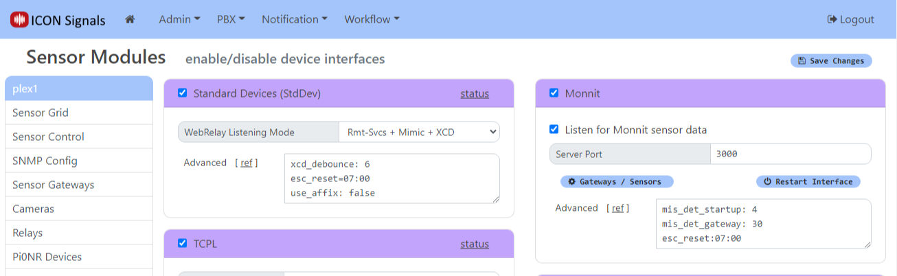
ICON Signals supports different families of sensor devices, each of which can be enabled or disabled in the Workflow > Sensor Modules page. The Standard Device Interface is used for devices which are not directly configured by ICON Signals itself. Examples include passive environmental sensors, webcams, and other devices which are configured outside of ICON Signals and which simply send data to ICON Signals.
ControlByWeb devices are handled within the Standard Device Interface. When this interface is enabled, Signals does the following with respect to webrelay devices:
(Note: Changing the Remote Services port from 6506 to another value is not recommended and should only be done in consultation with ICON support.)
WebRelay devices that do not have Remote Services (e.g. the 1-input, 1-relay WebRelay X-WR-1R12) do not use the WebRelay listener.
An X-400 and its expansion modules are connected together by a ribbon cable and typically attached to a DIN rail.
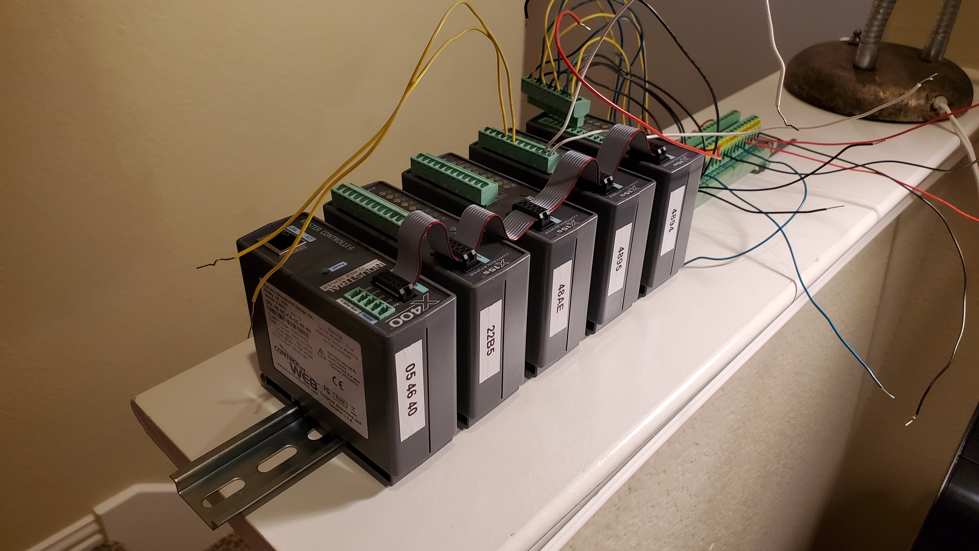
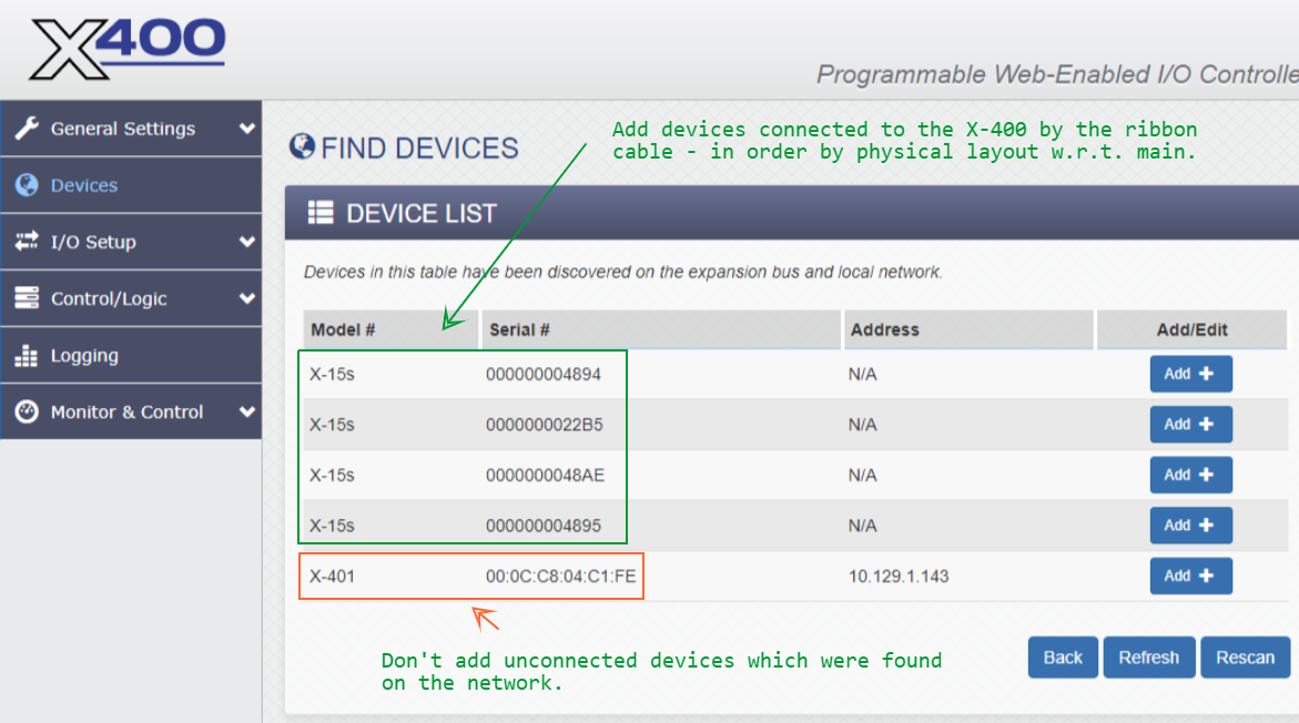
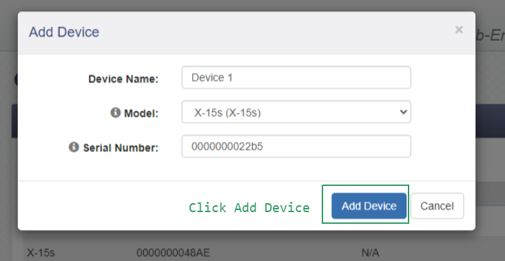
The "aftermarket" labels on the tops of the units show the last six digits of the X-400 MAC and the last four digits of the X-15s serial number. This is strongly recommended - you will need those serial numbers when configuring the X-400.
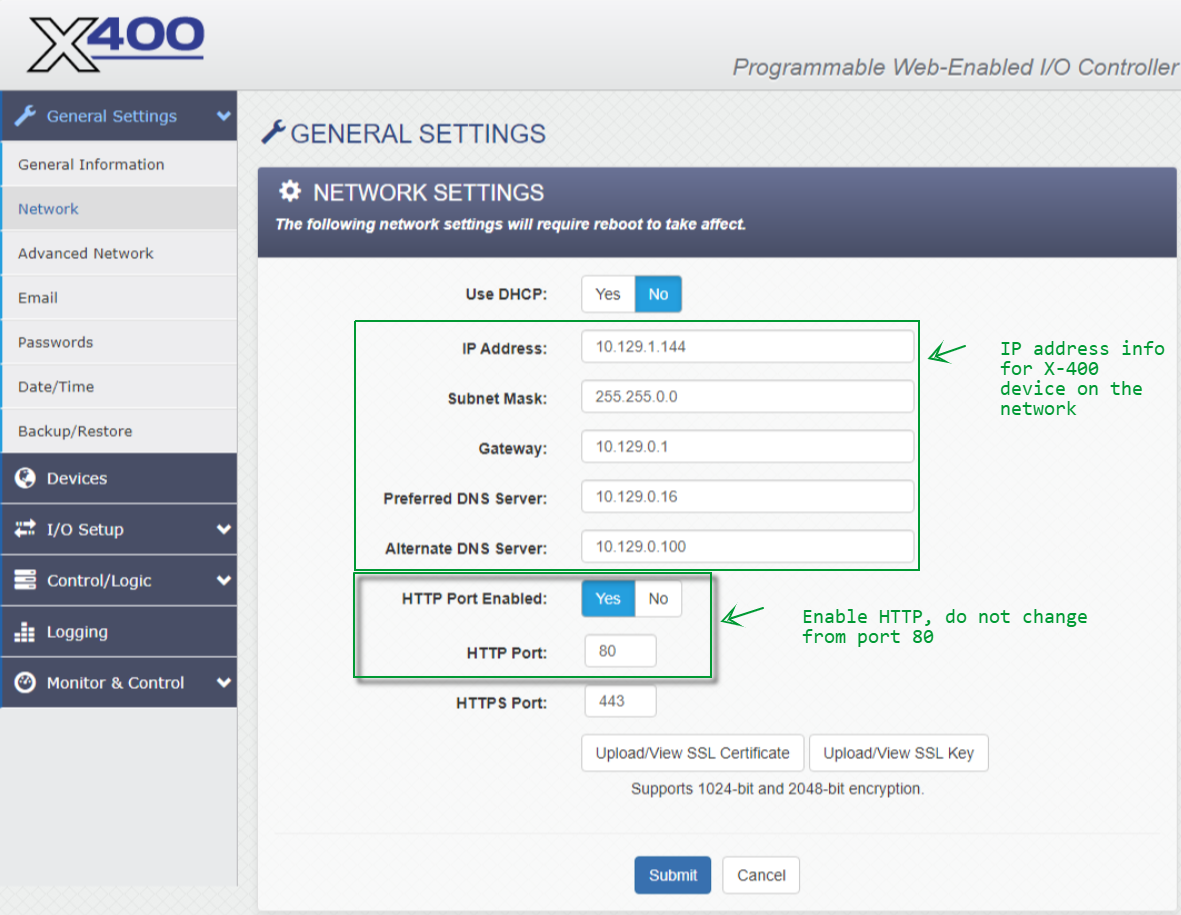
Configure the WebRelay device to be on the same network as the ICON Signals server. Refer to the manual for details.
For all ControlByWeb devices, the setup page is {ip-address}/setup.html
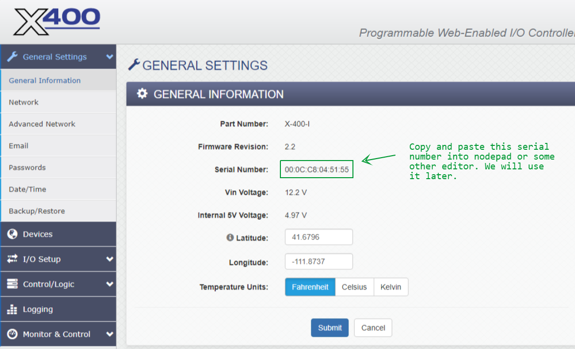
Follow the "Quick-Start Guide" shipped with the X-400 to get it on the same network as the ICON Signals server. Then continue reading this section.
The X-400 web UI pages are functionally similar to those of the X-401 and X-405.
Screenshots from the X-400 setup pages follow with relevant comments.
When making any changes, you must click the Submit button at the bottom of the page.
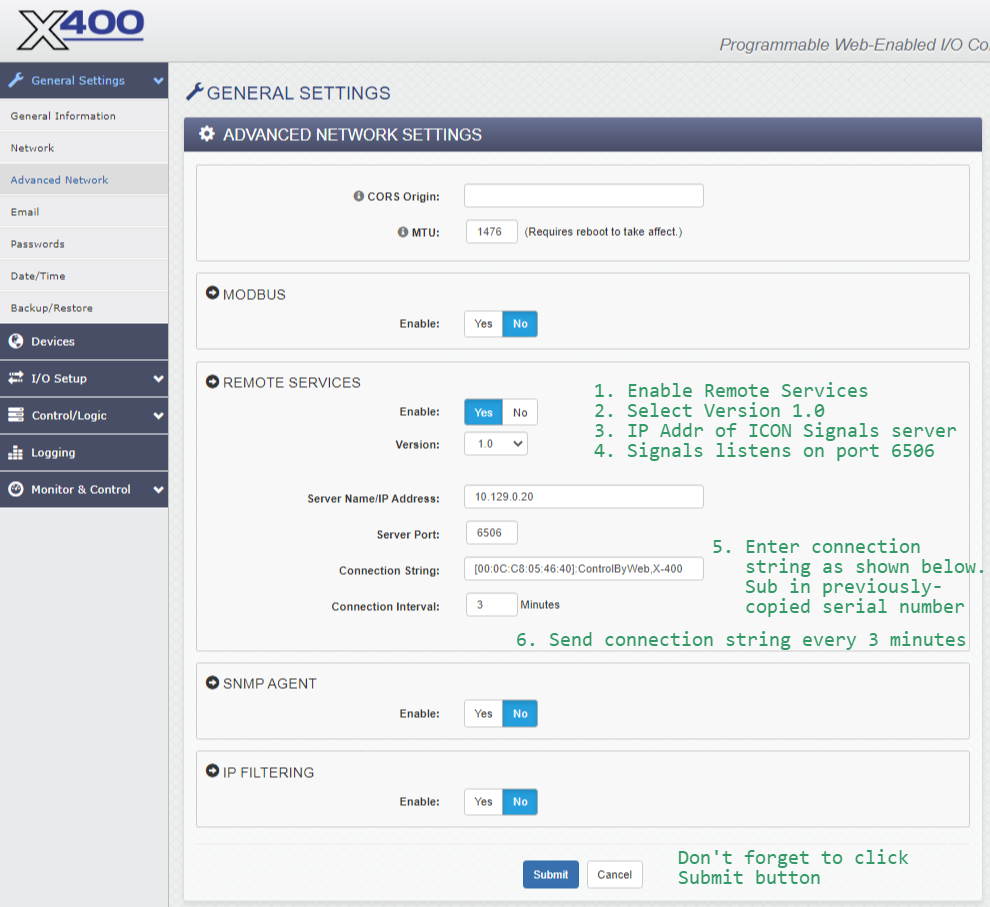
When Remote Services is enabled, the WebRelay makes a TCP connection to the given IP address and port and sends the connection string. After that it periodically sends the connection string to the destination server. ICON Signals expects to find the MAC address in the connection string, so please configure it as shown in the above screenshot.

Sync with an NTP server on a fairly frequent basis. Control/Logic Tasks compute and display the time when their next action will be executed.
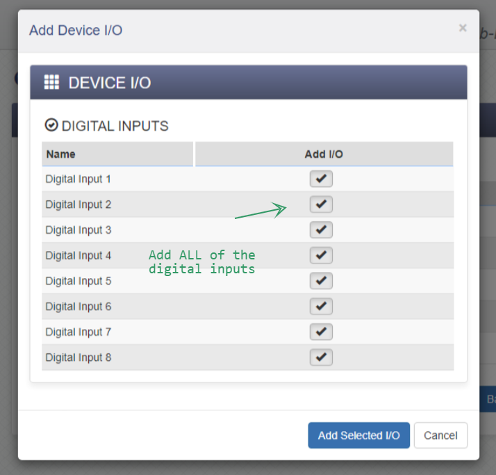
The Digital Inputs page should show the correct number of Local Device Input numbers.
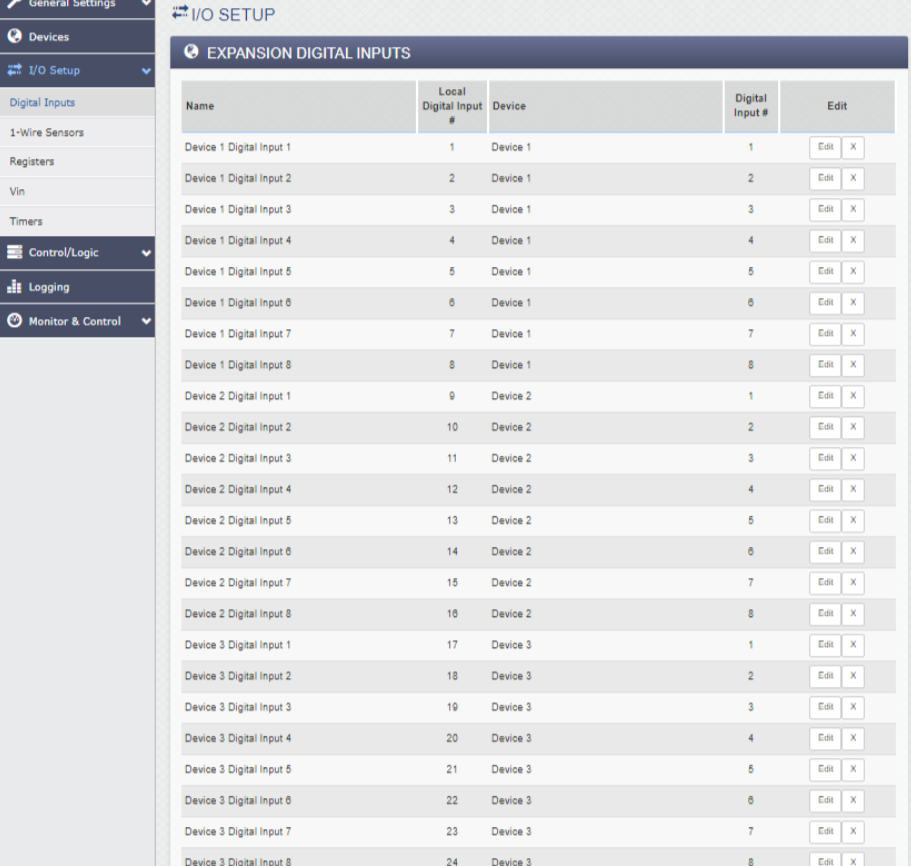
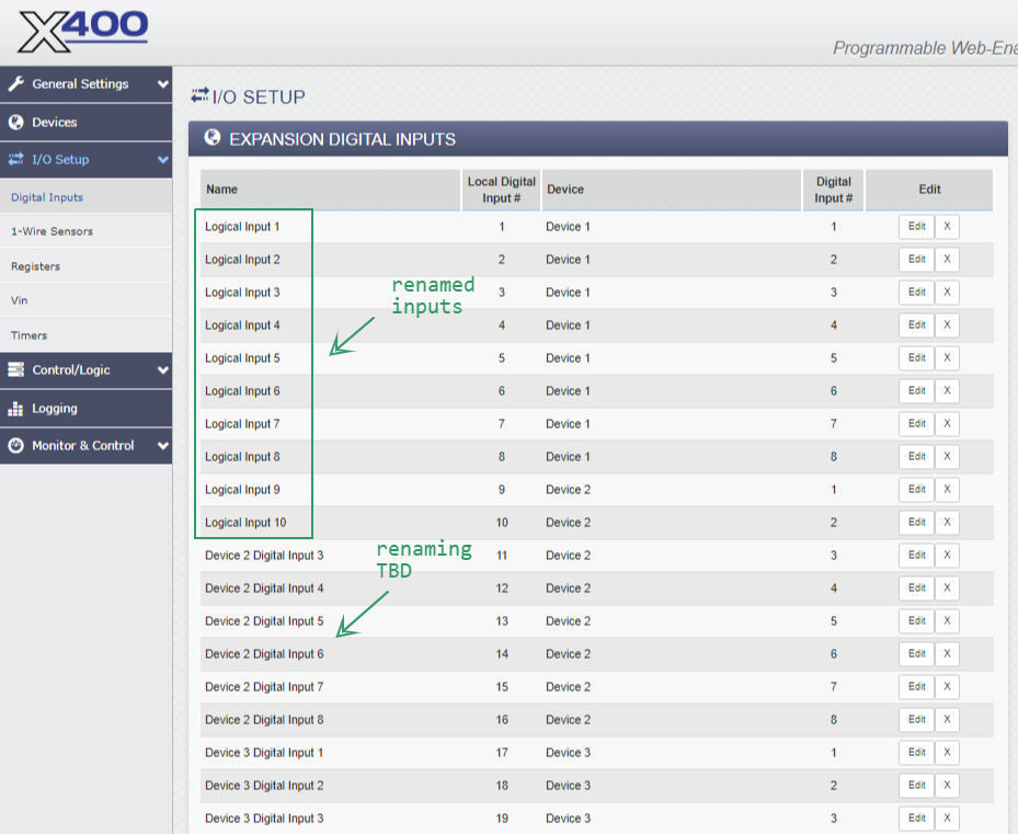
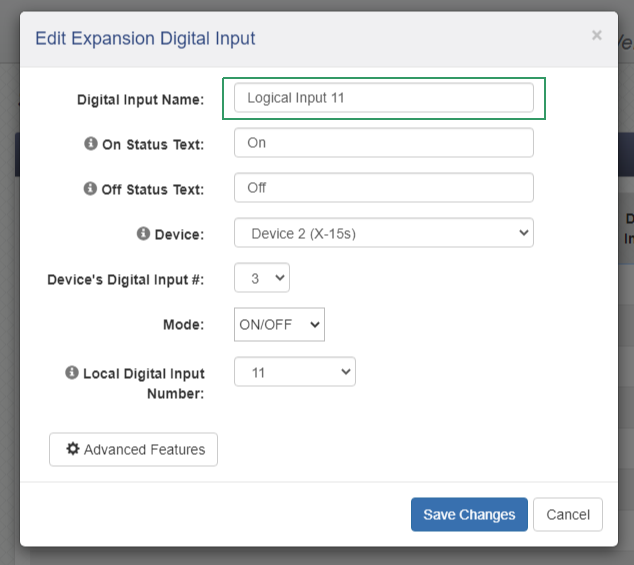
Technically, nothing has to be done in this section. However, it is useful to rename the inputs using their logical (local) number. The logical number is what Signals receives when state data is sent via Remote Services. In the case of 32 inputs, elements digitalInput1 thru digitalInput32.
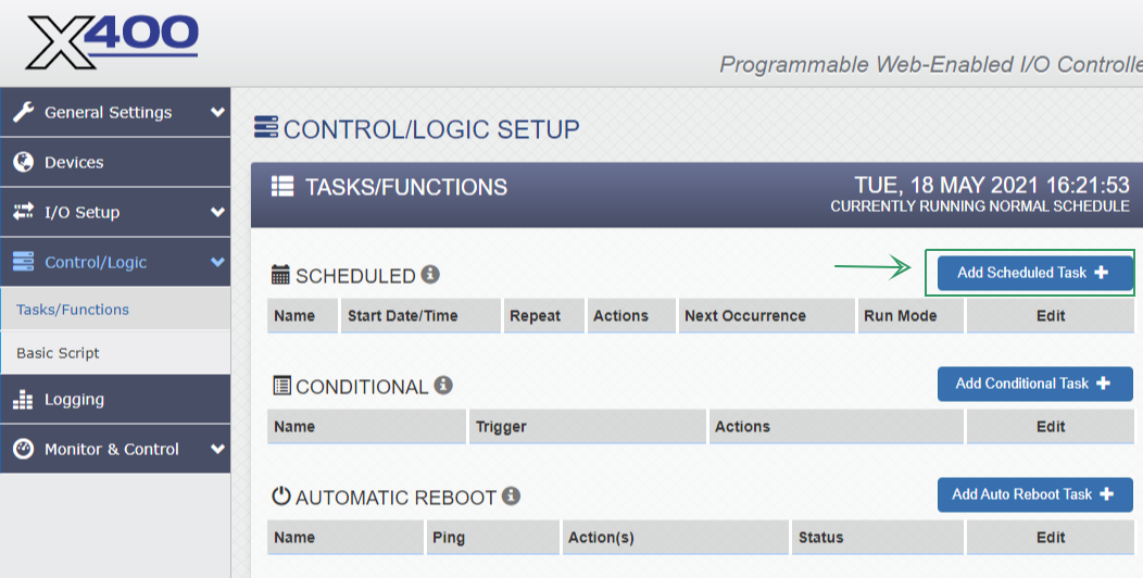
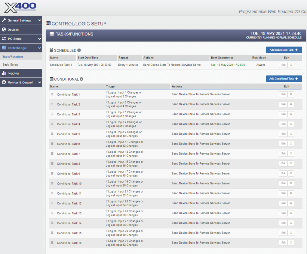
The Control/Logic Setup > Tasks/Functions page is critical to the integration with ICON Signals. Basically we configure the X-400 to send state information when anything changes. Rules within Signals will determine what happens next. For example, a rule might only perform an action when Digital Input 1 is turned ON.
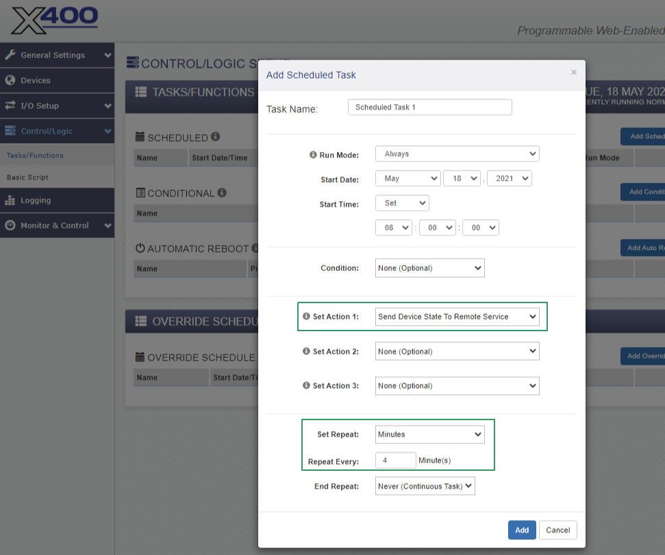
Create a scheduled task to send the device state to Signals every few minutes via Remote Services. (See screenshots below.)
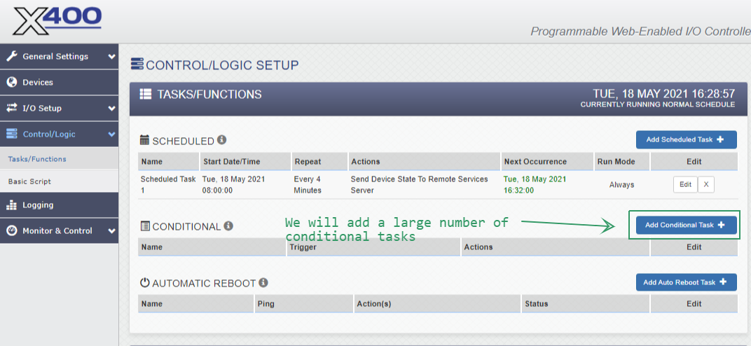
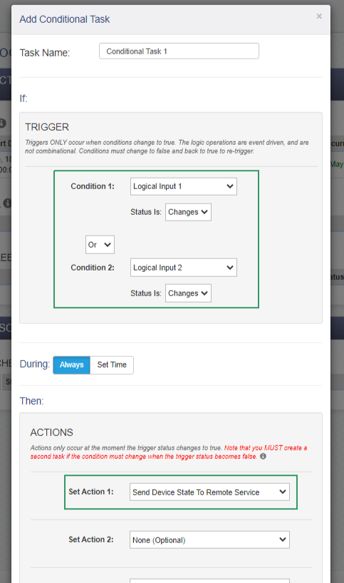
As previously mentioned, we want to send device state to Signals whenever a digital input state changes. Each Conditional Task allows us to configure this for two inputs. See screenshots below.
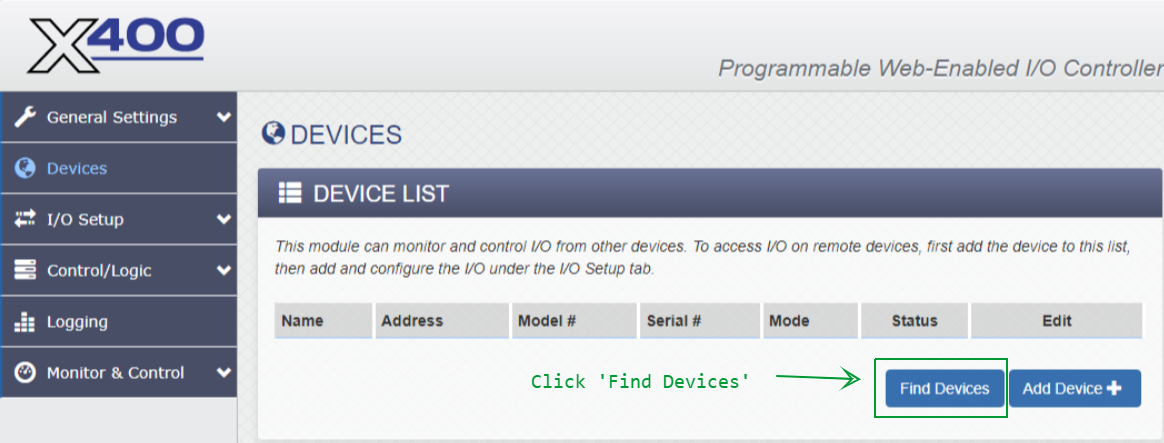
When ICON Signals receives data for an unknown WebRelay device, it creates entries in the database for that device and all of its I/O channels. For an X-400 with four X-15s modules, that results in a Workflow > Sensor Grid device with 32 rows of I/O data channels.
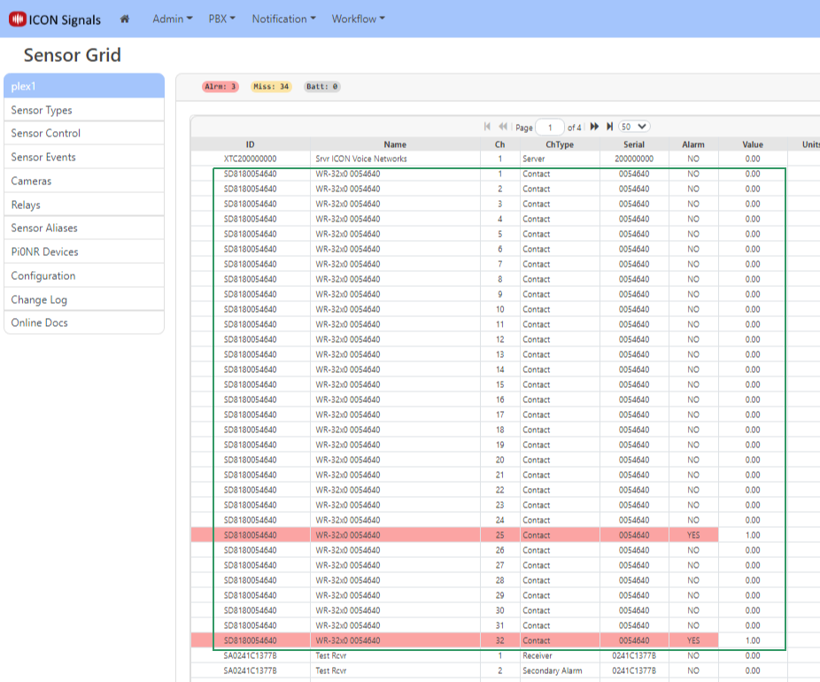
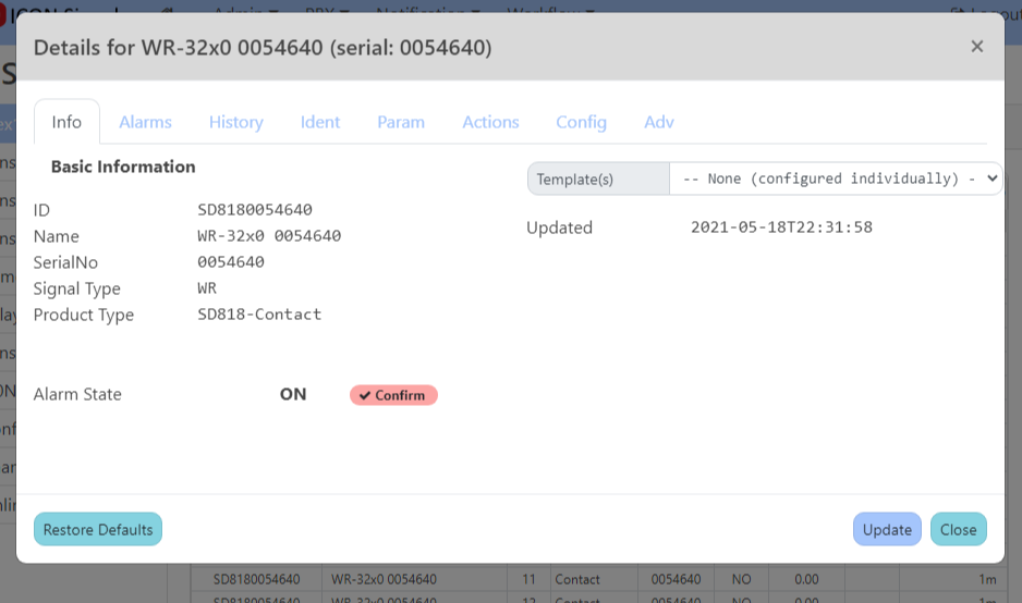
Click on any of the grid rows for the X-400 to open the device dialog.
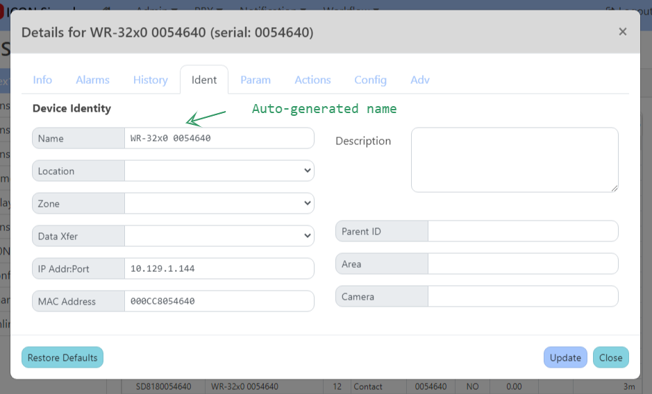
In the Ident tab, you may change the name of the device to something meaningful for the project. We typically create rules which match against the device name - especially if there are multiple webrelay devices at the site.
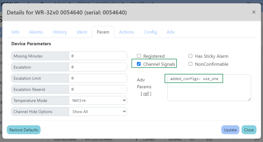
In the Config tab, we set the alarm mode for the first two I/O channels. In the Param tab, we check the Channel Signals box and set an Advanced parameter.
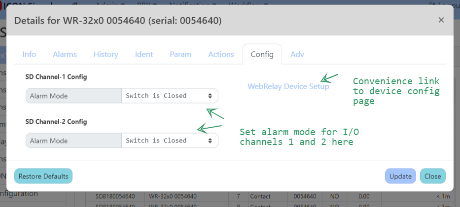
Within ICON Signals, every device enters alarm state and an ON signal is raised whenever any of its inputs enters alarm state. The device leaves alarm state and an OFF signal is raised when all of the inputs leave alarm state.
This is not helpful for a device with multiple I/O channels when we want to monitor those channels independently. That's where Channel Signals come in. When enabled, ICON Signals will raise ON and OFF signals for each individual channel as it enters and exits alarm state.
The advanced parameter added_configs: use_one means that I/O channel 3 and above will use the alarm mode configuration for channel 1.
When a WebRelay device or I/O channel enters or exits alarm state, ICON Signals raises signals with the following names:
| event | signame |
|---|---|
| device enters alarm state (at least one channel in alarm state) | WR-ON-%{device name}% |
| I/O channel enters alarm state for a device w/ Channel Signals enabled | WR-ON-CH{nbr}-%{device name}% |
| device exits alarm state (last alarm state channel leaves alarm state) | WR-OFF-%{device name}% |
| I/O channel exits alarm state for a device w/ Channel Signals enabled | WR-OFF-CH{nbr}-%{device name}% |
Example signal names for the device shown in previous screenshots are:
  WR-ON-%WR-32x0 0054640%
  WR-OFF-%WR-32x0 0054640%
  WR-OFF-CH1-%WR-32x0 0054640%
  WR-ON-CH25-%WR-32x0 0054640%
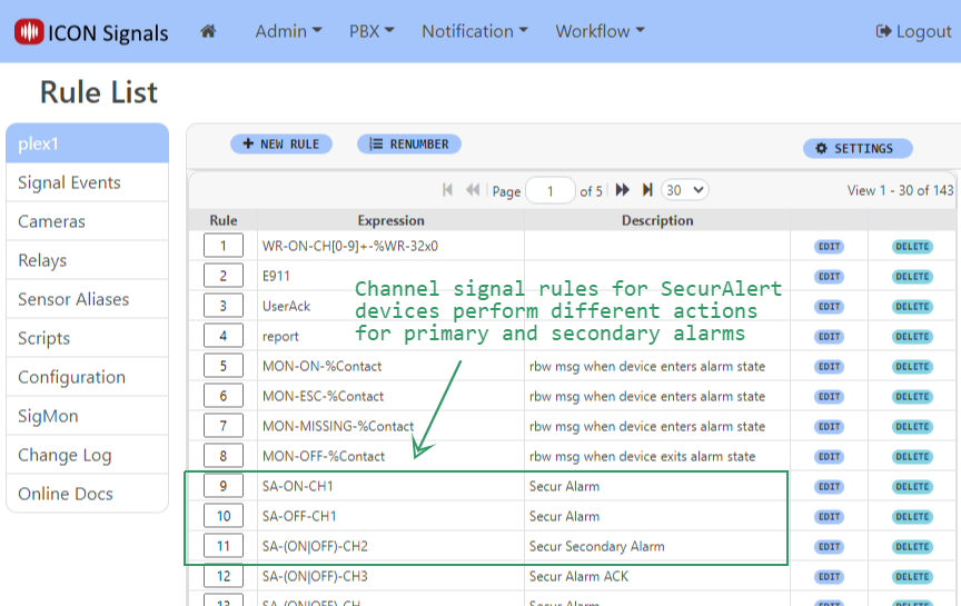
For some devices it is desirable to write separate rules for each I/O channel to perform different actions.
For a device with a large number of inputs, it is usually better to have a small number of channel rules (maybe just one) which match against multiple channel signals.
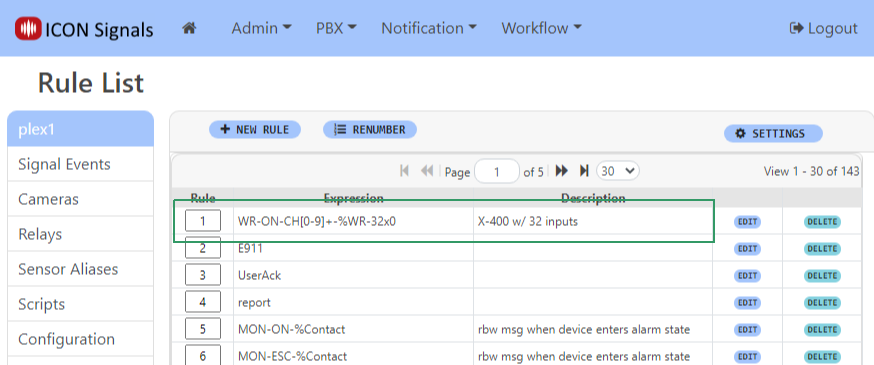
Regular Expression matching is used. The above rule will match with an ON channel signal for any WebRelay device with a name beginning with WR-32x0.
In this example, we will configure a rule to display a basic Rainbow message for X-400 contact closures.
When a signal is raised, the ICON Signals application searches the Rule List sequentially looking for a rule expression that matches the signal name.
If a match is found, the rule - which is essentially a script - is executed by the Signals Rule Engine.
Clicking on the Edit button for a rule in the Rule List displays the rule dialog.
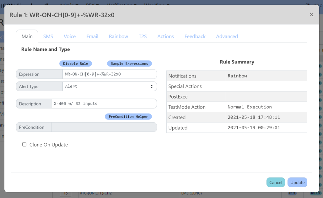
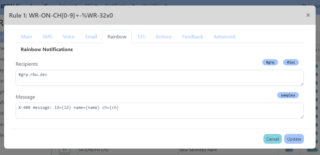
A contact closure on input 25 executes this rule and generates the following Rainbow message.

The {id}, {name} and {ch} tags were replaced with the Device ID, Device Name and Channel Number respectively.
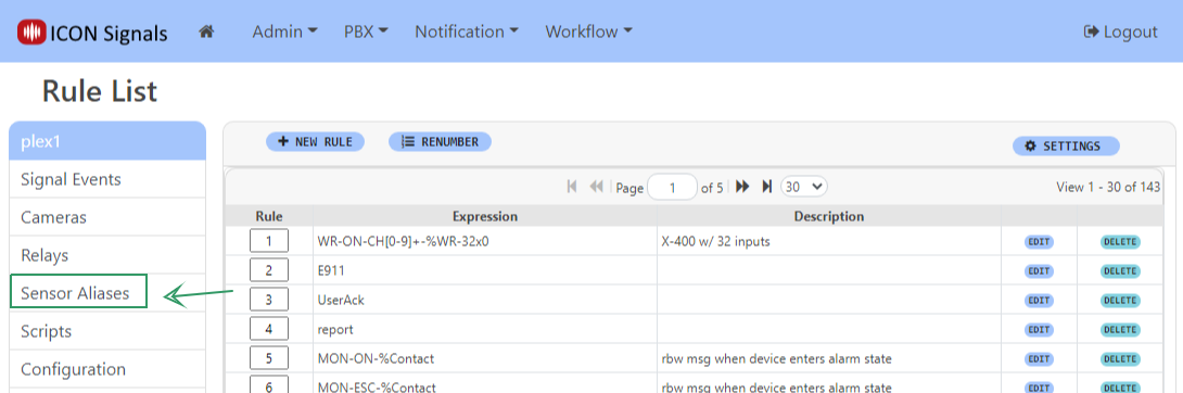
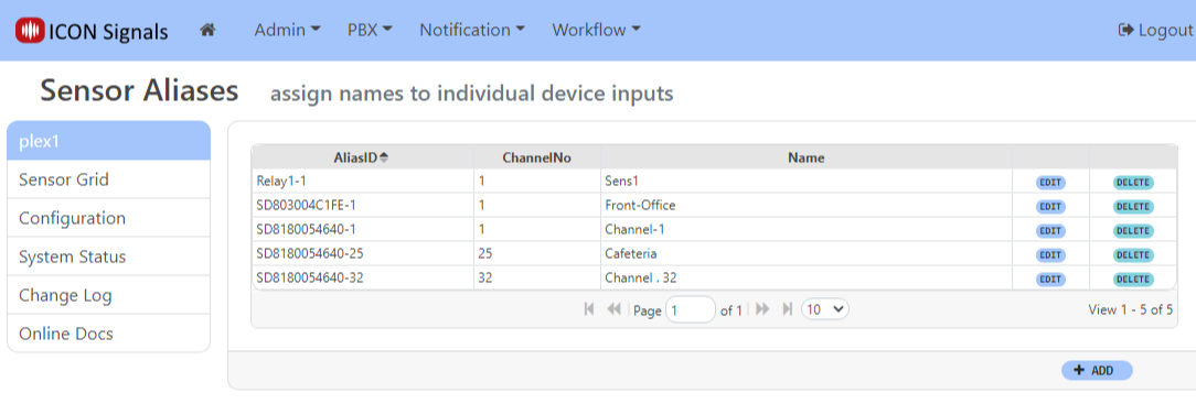
We can replace the Device Name with a more useful sensor alias which describes that specific input. Click on the Sensor Aliases navigate link on the Rule List page.
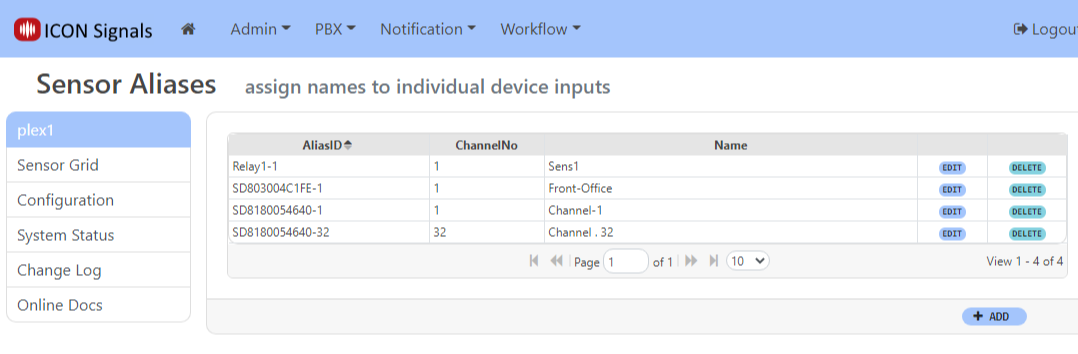
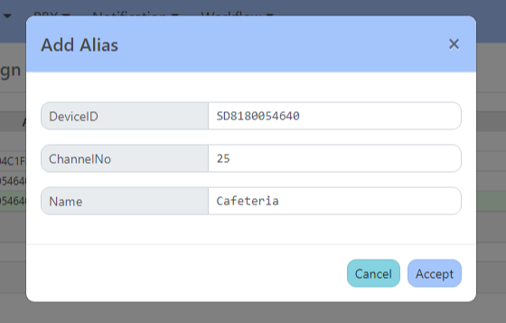
Click the ADD button to create a new alias for a given device id (in this case the X-400) and I/O channel.
Repeating the contact closure test for input 25 generates the following Rainbow message:

This example generates a Rainbow message, but the process also works for SMS and Email messages.
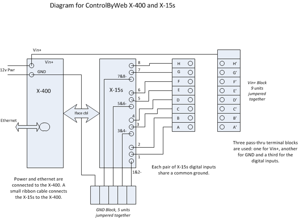
This example diagram is for an X-400 connected to a single X-15s expansion module.
2018-2022 ICON Voice Networks